Low Frequency Broadband Antennas for EMC Testing

An electromagnetic compatibility and broadband antenna technology, which is applied in the direction of antenna coupling, antenna grounding device, antenna grounding switch structure connection, etc., can solve the problems of large antenna size and large effective radiation power, and meet the requirements of reducing test transmission power and improving field The uniformity of intensity amplitude and field intensity, and the effect of improving test accuracy

Active Publication Date: 2021-03-23
南京容向测试设备有限公司
View PDF4 Cites 0 Cited by
  • Summary
  • Abstract
  • Description
  • Claims
  • Application Information

AI Technical Summary

Problems solved by technology

[0004] Technical problem: the present invention proposes a low-frequency broadband antenna for electromagnetic compatibility testing, which not only solves the problem of large antenna size, but also ensures that the antenna has good standing wave and radiation performance at low frequency and wide frequency band, and does not need a feeding matching network Or balun, which reduces the loss of response and has a large effective radiation power; and avoids the adverse effects of antenna height on the test, reduces the adverse effects of ground reflection on the uniformity of field strength in the test area of ​​the test piece, and makes the test piece on the ground , whether in the near or far zone of the antenna, can always be within the main lobe of the antenna

Method used


Image

  • Low Frequency Broadband Antennas for EMC Testing
  • Low Frequency Broadband Antennas for EMC Testing

Examples


Embodiment Construction

[0019] The specific implementation manners of the present invention will be further described below in conjunction with the drawings and examples. The specific embodiments described here are only used to explain the present invention, and the present invention cannot be limited by the specific embodiments.

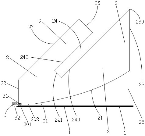
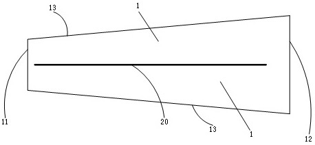
[0020]The embodiment that the present invention adopts is: the low-frequency broadband antenna that is used for electromagnetic compatibility test comprises grounding conductor plate 1, pole plate 2 and joint 3; Pole plate 2 is made with the good material of electrical conductivity; Vertical, pole plate 2 and ground conductor plate 1 constitute two poles of the antenna; at antenna input 201, inner conductor 31 of joint 3 is connected with pole plate 2, and outer conductor 32 of joint 2 is connected with ground conductor plate 1; pole plate 2 The length of the vertical projection 20 on the grounding conductor plate 1 is not less than half of the maximum operating wavelength...


PUM


Abstract

The low-frequency broadband antenna used for electromagnetic compatibility testing mainly includes a ground conductor plate (1), a pole plate (2) and a joint (3); the ground conductor plate (1) is laid flat on the ground, the pole plate (2) and the ground conductor plate (1) Vertical, the polar plate (2) and the ground conductor plate (1) constitute the two poles of the antenna; the length of the vertical projection (20) of the polar plate (2) on the ground conductor plate (1) is not less than the maximum operating wavelength 1 / 2 of ; the shape of the pole plate (2) is an irregular polygon, the shape of the exponential edge (21) of the polygon is an exponential shape, and the shape of the remaining edges is a straight line; the notch (24) extends into the pole plate (2) )internal. The antenna is small in size, light in weight and low in installation position, which is not only easy to install, but also reduces the requirements for test transmission power, reduces the cost of test equipment and test operation costs, and improves the uniformity of test field strength, test repeatability and Repeatability.

Description

technical field [0001] The invention relates to electromagnetic compatibility testing, in particular to a low-frequency broadband antenna for electromagnetic compatibility testing. Background technique [0002] The purpose of electromagnetic compatibility testing is to test the sensitivity of the tested electrical and electronic products or systems (collectively referred to as test items) to external electromagnetic fields. In the test, the transmitting antenna of the electromagnetic compatibility test needs to generate a uniform electromagnetic field in the area of ​​the test piece. According to the test standard ISO 11451-2 (Road Vehicle Vehicle Immunity Test Method for Narrowband Radiated Electromagnetic Energy Part 2: External Radiation Source Method), the working frequency band of the field generating device (transmitting antenna) used for the test is 20MHz to 18GHz . [0003] In the frequency range of 20MHz to 220MHz, although the logarithmic periodic broadband anten...

Claims


Application Information

Patent Timeline
Patent Type & Authority Patents(China)
IPC IPC(8): H01Q1/36H01Q1/52H01Q1/48H01Q1/50
CPCH01Q1/36H01Q1/48H01Q1/50H01Q1/52
Inventor 周文龙沈学其范文远沈伟杰
Owner 南京容向测试设备有限公司
Why Eureka
Try Eureka