Display driving module, control method thereof and display driving system

A technology for driving modules and displays, applied to static indicators, instruments, etc., which can solve the problems of gray scale and refresh rate limitation, high noise, and easy to exceed the specification, etc.

Active Publication Date: 2021-02-02
MINIDSN INC
View PDF10 Cites 1 Cited by
  • Summary
  • Abstract
  • Description
  • Claims
  • Application Information

AI Technical Summary

Problems solved by technology

[0006] like Figure 10 and Figure 11 As shown, when the display system includes a plurality of LED driving modules 90, and each of the LED driving modules 90 respectively outputs a driving signal, since each of the LED driving modules 90 receives the same clock signal input, such as the gray scale clock signal or the driving information clock, that is, the source of the clock signal is the same, so the driving signals of each LED driving module 90 are in the same phase, and in each output cycle, the rising edge of the signal will be synchronized. The duty cycle of the driving signals is the same, and the falling edges of the signals will also be synchronized, so the occurrence time of the signal glitches generated by each driving signal during switching will also be synchronized, resulting in the superposition effect of the noise on the circuit board. Big
In addition, based on the edge of the same clock signal received by each of the LED driving modules 90, the frequency of the gray-scale clock signal of each of the LED driving modules 90 is the same, so that the electromagnetic interference (EMI) frequency band generated by each of the driving signals is too concentrated. , its EMI spectrum will produce multiple spurs, and the EMI spurs are likely to exceed the EMI specifications for electronic products in the regulations, resulting in the product as a whole not conforming to the specifications
[0007] Based on the above, the gray scale and refresh rate of the existing LED display drive module are limited by receiving the gray scale clock signal from the outside, and further make the noise generated by the multiple drive signals on the display circuit board too high
If the driver module has a built-in phase-locked loop unit to generate GCLK, there will still be problems of EMI spectrum concentration, so it is easy to exceed the specification

Method used


Image

  • Display driving module, control method thereof and display driving system
  • Display driving module, control method thereof and display driving system
  • Display driving module, control method thereof and display driving system

Examples


Embodiment Construction

[0051] The technical means adopted by the present invention to achieve the intended invention purpose are further described below in conjunction with the drawings and preferred embodiments of the present invention.

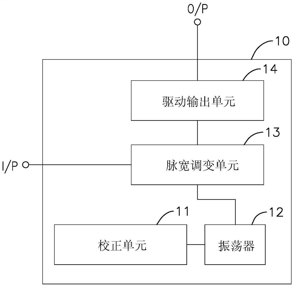
[0052] see figure 1 As shown, the present invention provides a display driving module 10, which has a driving information input terminal I / P and a driving signal output terminal O / P, and includes a calibration unit 11, an oscillator 12, a pulse width modulation Unit 13 and a drive output unit 14, the correction unit 11 stores a frequency correction information, the oscillator 12 is electrically connected to the correction unit 11 to receive the frequency correction information and generate a gray scale clock signal accordingly, the gray scale clock signal The frequency is within a target frequency range; the pulse width modulation unit 13 is electrically connected to the driving information input end to receive a driving information, and is electrically connected...


PUM


Abstract

The invention provides a display driving module, a control method thereof and a display driving system. The display driving module executes a control method and comprises an adjustable frequency oscillator and a correction unit, and the correction unit outputs frequency correction information to enable the adjustable frequency oscillator to generate a gray scale clock signal with the frequency within a target frequency range. The pulse width modulation unit generates a pulse width control signal according to the gray scale clock signal and driving information, and a driving output unit receives the pulse width control signal and outputs a driving signal according to the pulse width control signal; a display driving system comprises more than two driving modules, and the two driving modulesrespectively comprise non-synchronous oscillators with different frequencies, so that the two gray-scale clock signals cannot be switched synchronously, high-frequency noise of the two driving signals is prevented from being generated at the same time, EMI (electro-magnetic interference) frequency spectrums of the driving signals can be dispersed. And the glitch noise of the frequency spectrum ofthe EMI at a specific frequency is reduced.

Description

technical field [0001] The invention relates to a driving module, a control method and a driving system, in particular to an LED display driving module, its control method and an LED display driving system. Background technique [0002] The LED (Light-Emitting Diode; LED) display is driven by a display drive system to generate images. An LED display includes at least one LED unit and a display drive module. The drive module generates a current signal according to a brightness control signal, so that the The current signal passes through the LED unit, and the LED unit generates light of corresponding intensity according to the intensity of the current signal. Existing display driver modules generally use pulse width modulation (Pulse Width Modulation; PWM) to control each LED unit to produce different degrees of brightness. More specifically, the PWM mechanism utilizes the persistence of vision of the human eye, that is, when the flickering frequency of a light source is gre...

Claims


Application Information

Patent Timeline
IPC IPC(8): G09G3/32
CPCG09G3/32
Inventor 史富洋
Owner MINIDSN INC
Why Eureka
Try Eureka