
Pulsed light driven focused ultrasonic transmitter

A pulsed light, focused technology, used in the analysis of solids using sonic/ultrasonic/infrasonic waves, material analysis using sonic/ultrasonic/infrasonic waves, instruments, etc. good resolution

Active Publication Date: 2021-02-02
ZHEJIANG LAB
View PDF7 Cites 0 Cited by
  • Summary
  • Abstract
  • Description
  • Claims
  • Application Information

AI Technical Summary

Problems solved by technology

However, the highest frequency that piezoelectric transducers can achieve is generally hundreds of MHz, which is difficult to further improve due to the limitation of hardware structure.
In addition, traditional ultrasonic transmitters are based on piezoelectric materials, and the center frequency and bandwidth of ultrasonic pulses generated are fixed and cannot be adjusted. It is difficult to meet the requirements of different applications for resolution and penetration.
Therefore, industrial ultrasonic microscopes need to be equipped with a batch of ultrasonic generators with different center frequencies, and the cost is relatively high.

Method used


Image

  • Pulsed light driven focused ultrasonic transmitter
  • Pulsed light driven focused ultrasonic transmitter

Examples


Embodiment 1

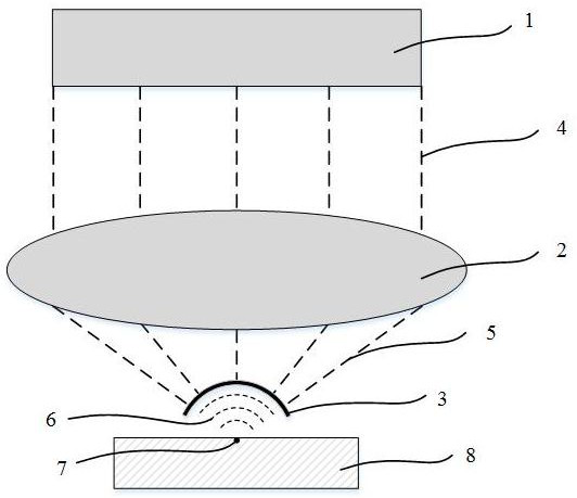
[0020] Such as figure 1 As shown, a focused ultrasonic transmitter driven by pulsed light includes a pulsed light source 1, an objective lens 2 and a light-absorbing film 3. The light-absorbing film 2 is a spherical crown and is made of a material with strong light-absorbing properties. The light-absorbing film 2 After absorbing light energy, photoacoustic effect can be generated and ultrasonic waves can be focused; the optical path of the objective lens 2 is implemented in a transmission type, which uniformly irradiates the pulsed light emitted by the pulse light source 1 to the surface of the light-absorbing film 2, and the light-absorbing film 2 is illuminated by the light. 2. The focus of the pulsed light on the surface coincides with the spherical center of the light-absorbing film 2; the pulsed light source 1 is a pulsed laser, a pulsed LED light source or a flash lamp, and its pulse width is variable.

[0021] The specific principles are as follows:

[0022] The pulse ...

Embodiment 2

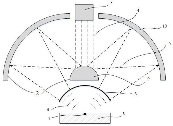
[0024] Such as figure 2 As shown, a focused ultrasonic transmitter driven by pulsed light includes a pulsed light source 1, an objective lens 2 and a light-absorbing film 3. The light-absorbing film 2 is a spherical crown and is made of a material with strong light-absorbing properties. The light-absorbing film 2 After absorbing light energy, photoacoustic effect can be generated and ultrasonic waves can be focused; the optical path of the objective lens 2 is implemented in a reflection type, consisting of a first reflector 9 and a second reflector 10, and the two reflectors emit the pulsed light source 1 The pulsed light irradiates the surface of the light-absorbing film 2 evenly, and the focus of the pulsed light irradiated on the surface of the light-absorbing film 2 coincides with the center of the sphere of the light-absorbing film 2; the pulsed light source 1 is a pulsed laser, a pulsed LED light source or a flash lamp, Its pulse width is variable.

[0025] The specifi...


PUM


Abstract

The invention relates to a pulsed light driven focused ultrasonic transmitter, which comprises a pulsed light source, an objective lens and a light absorption film, and the light absorption film is spherical crown-shaped, and can generate a photoacoustic effect and focus ultrasonic waves after absorbing light energy; the objective lens evenly irradiates pulsed light emitted by the pulsed light source to the surface of the light absorption film, and the focus of the pulsed light irradiated to the surface of the light absorption film coincides with the sphere center of the light absorption film.The ultrasonic transmitter can transmit high-frequency ultrasonic waves, the center frequency of the ultrasonic waves is adjustable, and the requirements of ultrasonic microscopes of different applications for resolution and penetrating power are met.

Description

technical field [0001] The invention relates to an ultrasonic transmitter, in particular to a focused ultrasonic transmitter driven by pulsed light. Background technique [0002] Ultrasound microscopy is a device that exploits differences in the acoustic properties of the internal structure of a sample for imaging. Since ultrasonic waves are more penetrating than light waves, ultrasonic microscopes can image opaque objects and detect the inner structure of samples without damaging the surface of the sample. At present, ultrasonic microscopes are mainly used in biomedical imaging, non-destructive testing of microelectronic integrated circuits, and materials testing. [0003] The performance of an ultrasonic microscope is closely related to the frequency of the ultrasonic waves. The higher the ultrasonic frequency, the shorter its wavelength. According to the Rayleigh criterion, the resolution of the microscope will be higher, but the penetrating power will be weaker. Tradi...

Claims


Application Information

Patent Timeline
IPC IPC(8): G01N29/06G01N29/24
CPCG01N29/0681G01N29/2418
Inventor 施钧辉尹永刚任丹阳高远
Owner ZHEJIANG LAB
Learn More