Heat supply terminal condensate recycling process and using method thereof
A technology of condensate and process, applied in the field of condensate recovery process of heating terminal, can solve the problems of increasing working time, reducing working efficiency, strengthening staff strength, etc., and achieving the effect of improving working efficiency
- Summary
- Abstract
- Description
- Claims
- Application Information
AI Technical Summary
Problems solved by technology
Method used
Image
Examples
Embodiment 1
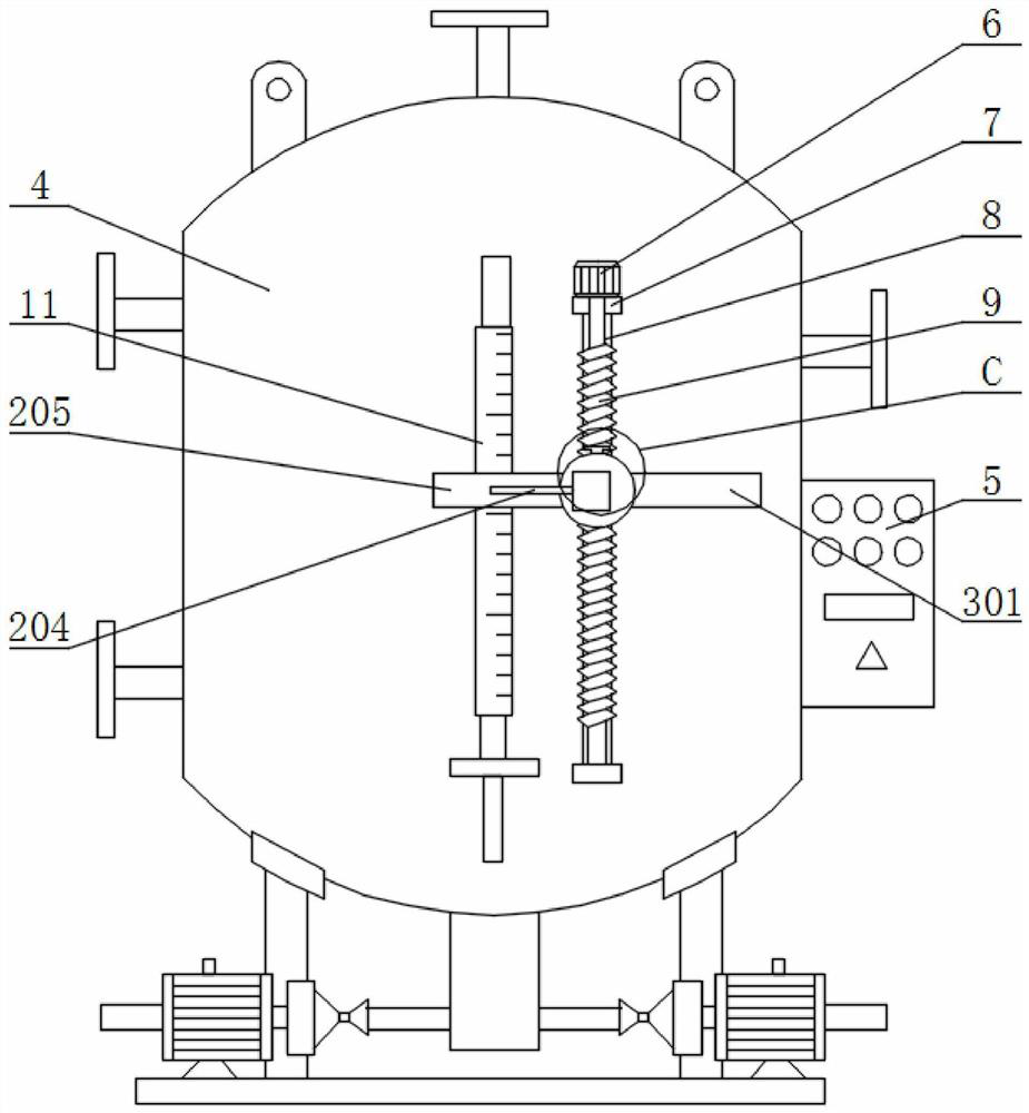
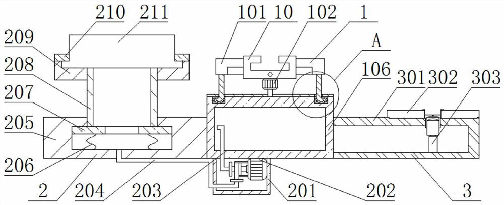
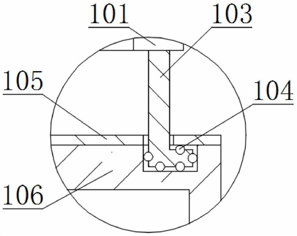
[0029] see Figure 1-6 , the present invention provides a technical solution:
[0030] A heat supply terminal condensate recovery process and its use method, comprising a condensate recovery device 4, the right end of the condensate recovery device 4 is fixedly connected with a controller 5, and the front end of the condensate recovery device 4 is fixedly connected with a liquid Position gauge 11, the front end of the condensate recovery device 4 is fixedly connected with a fixed block 7, the top of the fixed block 7 on the upper side is fixedly connected with a second motor 6, and the main shaft end of the second motor 6 is fixedly connected There is an adjusting screw 9, the outer side of the adjusting screw 9 is screw-connected with a slider 10, the inner side of the rear end of the slider 10 is slidably connected with a slide rail 8, and the slide rail 8 is fixedly connected with the condensate recovery device 4, the One end of the slide block 10 is fixed with a rotating ...
Embodiment 2
[0036] Embodiment 2 and Embodiment 1 will not go into details. The difference is that when the liquid level of the liquid level gauge 11 needs to be monitored in real time, the staff rotates the storage plate 106 by 180 degrees so that the monitoring device 3 is positioned at the level of the liquid level gauge. 11, while the staff controls the electric telescopic rod 303 with the camera 304 to gradually move backward through the controller 5, and the camera 304 also moves backward with the second limiting plate 305, and the second limiting plate 305 will Gradually move relative to the guide plate 306, so that the guide plates 306 on the left and right sides gradually move in the opposite direction under the action of the second limit plate 305, and at the same time, the moving plate 307 will also move along the position limit under the action of the guide plate 306. The shaft 311 moves until the camera 304 is removed from the inside of the fixed box 301, then the camera 304 ca...
PUM
 Abstract
Description
Claims
Application Information
 - Generate Ideas
- Intellectual Property
- Life Sciences
- Materials
- Tech Scout
- Unparalleled Data Quality
- Higher Quality Content
- 60% Fewer Hallucinations
Browse by: Latest US Patents, China's latest patents, Technical Efficacy Thesaurus, Application Domain, Technology Topic, Popular Technical Reports.
© 2025 PatSnap. All rights reserved.Legal|Privacy policy|Modern Slavery Act Transparency Statement|Sitemap|About US| Contact US: help@patsnap.com


