Electric loader transmission system and electric drive assembly

A transmission and loader technology, applied in the field of electric loader transmission, can solve problems such as easy overheating and sintering, low transmission efficiency, and large number of parts, and achieve the effects of reducing transmission noise, saving parts and system costs, and high transmission efficiency

Pending Publication Date: 2021-02-02
TOP GEAR POWERTRAIN TECH CO LTD
View PDF0 Cites 1 Cited by
  • Summary
  • Abstract
  • Description
  • Claims
  • Application Information

AI Technical Summary

Problems solved by technology

[0004] Traditional loader transmissions mostly adopt a 4-axis or 5-axis layout structure. There are many gears, shafts, and bearings, and there are many gear pairs meshing during transmission. This structure not only has a large number of parts, high cost, but also low transmission efficiency.
[0005] In addition, the traditional loader transmission uses a multi-plate clutch shift mechanism, which has a complex structure, high cost, and is easily damaged due to overheating and sintering
[0006] In addition, the external shift mechanism of the traditional loader transmission uses a hydraulic shift control valve, which has a complex structure, high cost, and is prone to sealing problems such as hydraulic leakage.

Method used


Image

  • Electric loader transmission system and electric drive assembly
  • Electric loader transmission system and electric drive assembly

Examples


Embodiment Construction

[0028] The present disclosure will be further described in detail below with reference to the drawings and embodiments. It can be understood that the specific implementation manners described here are only used to explain relevant content, rather than to limit the present disclosure. It should also be noted that, for ease of description, only parts related to the present disclosure are shown in the drawings.

[0029] It should be noted that, in the case of no conflict, the implementation modes and the features in the implementation modes in the present disclosure can be combined with each other. The present disclosure will be described in detail below with reference to the drawings and embodiments.

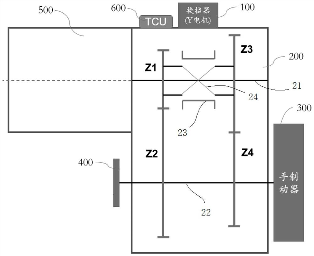
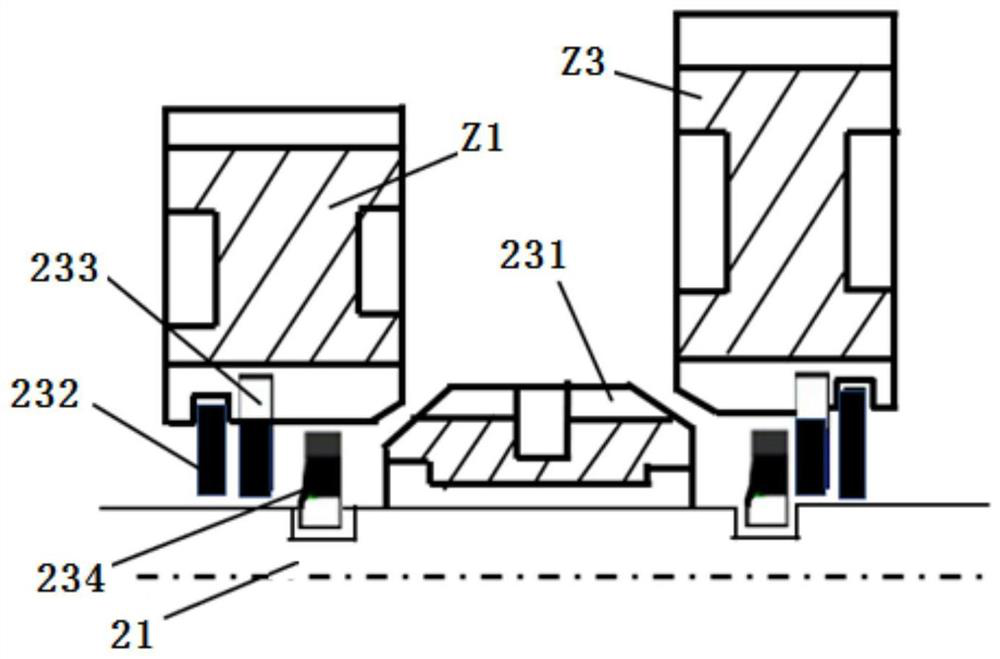
[0030] During the operation of the electric loader, the transmission should shift as little as possible, reduce the shifting action, and reduce the labor intensity of the driver, so as to improve efficiency. This requires the setting of the number of gears in the transmission sy...


PUM


Abstract

The invention provides an electric loader transmission system. The electric loader transmission system comprises a transmission body, a motor gear shifter and a transmission control unit, wherein thetransmission body comprises an input shaft, an output shaft, a sliding sleeve type gear shifting mechanism and a gear shifting fork; two gears are arranged on the input shaft. Two gears are arranged on the output shaft; the gear shifting fork is matched with the sliding sleeve type gear shifting mechanism, so that one pair of gears are engaged to form a low-speed gear, or the other pair of gears are engaged to form a high-speed gear; the motor gear shifter is connected with the gear shifting fork, and a motor is adopted for driving the gear shifting fork to move so as to drive the sliding sleeve type gear shifting mechanism to be switched between the low-speed gear and the high-speed gear; and the transmission control unit is electrically connected with the motor gear shifter and sends a gear shifting signal to the motor gear shifter. The electric loader transmission system meets the requirement for traction force of an electric loader and also meets the requirement for the vehicle speed, and high operation efficiency is obtained. The number of the gears, shafts and bearings in the two-shaft transmission arrangement structure form is smaller, the number of gear pairs is smaller, and the structure is simpler and more compact.

Description

technical field [0001] The present disclosure relates to the technical field of electric loader transmission, in particular to an electric loader transmission system and an electric drive assembly. Background technique [0002] The transmission system is an important part of the electric loader. The main task of the transmission system is to transmit the power from the drive motor through the meshing gear transmission, and drive the movement and operation of the loader or other construction machinery through the transmission shaft, axle and tires and other components. [0003] Since the operating environment of the loader is short-distance shoveling and other operations, in order to obtain the highest operating efficiency, the transmission should be shifted as little as possible during the operation, reducing the shifting action, reducing the shifting time, and reducing the driver's labor. strength to be able to increase efficiency and minimize energy consumption. Now the t...

Claims


Application Information

Patent Timeline
Patent Type & Authority Applications(China)
IPC IPC(8): F16H3/087F16H59/02F16H61/32F16H57/028F16H57/023F16H63/32H02K7/116
CPCF16H3/087F16H57/023F16H57/028F16H59/02F16H61/32F16H63/32F16H2003/0818H02K7/116
Inventor 李杉邓跃跃赵向阳陆海峰魏毅
Owner TOP GEAR POWERTRAIN TECH CO LTD
Why Eureka
Try Eureka