


Quick Research
Generate reliable direction feasibility study reports for your R&D in just a few steps.

Technical Q&A
Discover and master advanced knowledge NOW. Basics, ideas, possibilities, all at once.

Find Solutions
As an expert in R&D theories, this can generate solutions to your technical problems instantly.

Evaluate Feasibility
Analyze your overall solution with one click, know your potential R&D risks in advance.

Monitor Landscape
Get weekly tech updates, stay abreast of the latest tech innovations and key insights.
Manipulator handover station calibration method and device, equipment and storage medium
A calibration method and manipulator technology, applied in the direction of optomechanical equipment, manipulators, program-controlled manipulators, etc., can solve the problems of error amplification, long time-consuming, and many collision points
- Summary
- Abstract
- Description
- Claims
- Application Information
AI Technical Summary
Problems solved by technology
Method used
Image

Examples
Embodiment 1
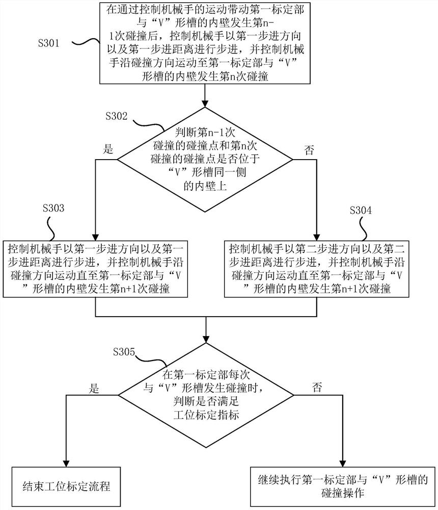
[0052] figure 1 The flow chart of the method for calibrating the manipulator handover station provided by Embodiment 1 of the present invention, this embodiment is applicable to the situation of calibrating the manipulator handover station, this method can be implemented by the manipulator handover station calibration device in the embodiment of the present invention implementation, the device can be implemented in software and / or hardware, such as figure 1 As shown, the manipulator handover station calibration method in the embodiment of the present invention specifically includes the following steps:
[0053] S301. After controlling the movement of the manipulator to drive the first calibration part to collide with the inner wall of the "V" groove for the n-1th time, control the manipulator to step in the first step direction and the first step distance, and control The manipulator moves along the collision direction until the first calibration part collides with the inner ...
Embodiment 2
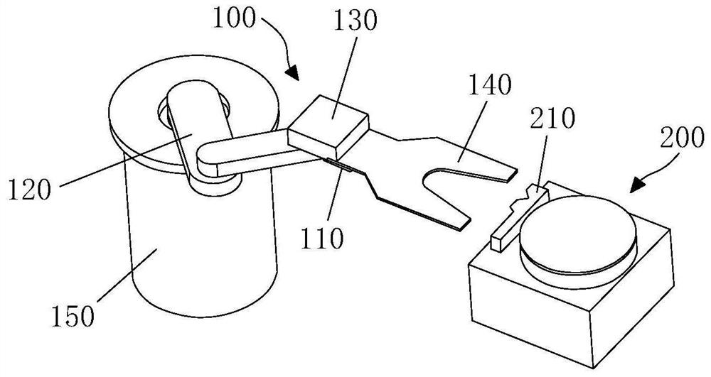
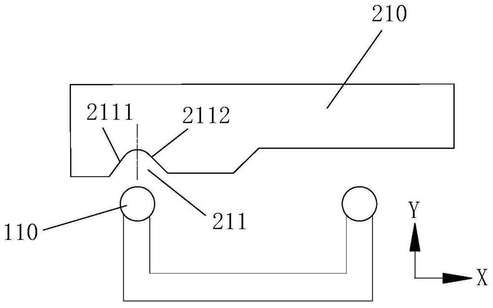
[0093] Embodiment 2 of the present invention provides a manipulator transfer station calibration device, the manipulator includes a first calibration part, the workpiece table includes a second calibration part corresponding to the first calibration part, the second calibration part has a "V" shaped groove, " The inner wall of the V"-shaped groove includes a first inner wall and a second inner wall on both sides. Figure 7 A schematic structural diagram of a manipulator transfer station calibration device provided in Embodiment 2 of the present invention, as shown in Figure 7 As shown, the device specifically includes:
[0094] The first control module 401 is used to control the movement of the manipulator to drive the first calibration part to collide with the inner wall of the "V"-shaped groove for the n-1th time, and then control the manipulator to move forward in the first step. direction and the first step distance, and control the manipulator to move along the collisio...
PUM
 Abstract
Description
Claims
Application Information
 - R&D Engineer
- R&D Manager
- IP Professional
- Industry Leading Data Capabilities
- Powerful AI technology
- Patent DNA Extraction
Browse by: Latest US Patents, China's latest patents, Technical Efficacy Thesaurus, Application Domain, Technology Topic, Popular Technical Reports.
© 2024 PatSnap. All rights reserved.Legal|Privacy policy|Modern Slavery Act Transparency Statement|Sitemap|About US| Contact US: help@patsnap.com