Active chilled beam air conditioner terminal

An air-conditioning terminal and active technology, applied in air-conditioning systems, heating methods, space heating and ventilation, etc., can solve the problems of flow velocity obstruction, reduce the risk of infection, increase the fresh air volume, etc., achieve stable air outlet direction and reduce infection Risk, the effect of increasing the fresh air volume

Active Publication Date: 2021-01-29
WUHAN UNIV OF TECH
View PDF8 Cites 0 Cited by
  • Summary
  • Abstract
  • Description
  • Claims
  • Application Information

AI Technical Summary

Problems solved by technology

But the terminal control device of existing chilled beam air-conditioning system all has deficiencies: (1) the terminal of existing chilled beam air-conditioning system is limited by the outer box, and the heat exchange area is small, is difficult to satisfy indoor cooling and heating demand; (2) Since the air flow at the air outlet of the terminal control device of the existing chilled beam air-conditioning system mainly relies on the air guide plate attached to the ceiling to supply air, the flow rate of the attached air supply will be hindered, and it is difficult to use this air supply method in tall spaces (3) When there is a disease that is infected through the respiratory tract such as the new crown epidemic, the return air cannot be closed in time to increase the fresh air volume and reduce the risk of infection

Method used


Image

  • Active chilled beam air conditioner terminal
  • Active chilled beam air conditioner terminal
  • Active chilled beam air conditioner terminal

Examples


Embodiment

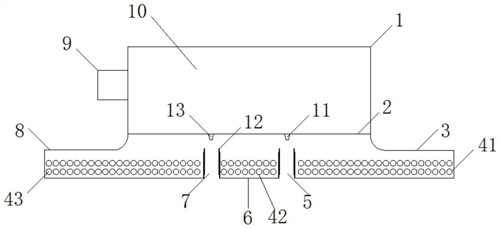
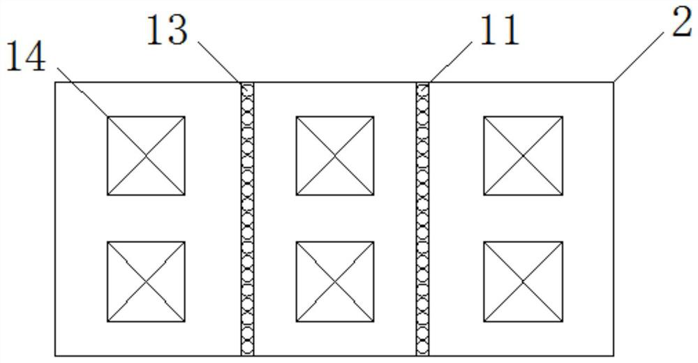
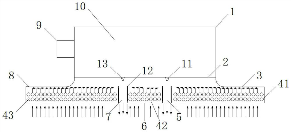
[0023] Such as figure 1 and figure 2 As shown, the embodiment of the present application provides an active chilled beam air conditioner terminal, which includes a box body, and the box body includes an outer box 1, an inner box 6, a left side box 8 and a right side box 3, and the left side The box 8, the inner box 6 and the right box 3 are sequentially arranged under the outer box 1 and the lower ends of the left box 8, the inner box 6 and the right box 3 are flush, and the outer box 1 is connected with a circular Air supply pipe 9, a static pressure chamber 10 is formed in the outer box 1, the outer box 1 is connected to the left and right side boxes, and the right side box 3, the inner box 6 and the left side box 8 are sequentially provided with the first A heat exchanger 41 , a second heat exchanger 42 and a third heat exchanger 43 . The treated primary air is sent into the static pressure chamber 10 through the circular air supply pipe 9 , and then ejected through the ...


PUM


Abstract

The invention discloses an active chilled beam air conditioner terminal. The active chilled beam air conditioner terminal comprises an outer box, an inner box, a left side box and a right side box, wherein the left side box, the inner box and the right side box are sequentially arranged below the outer box, the lower ends of the left side box, the inner box and the right side box are flush, a primary air circular air supply pipe is connected to the outer box, a static pressure cavity is formed in the outer box, the outer box is connected with the left side box and the right side box, and heatexchangers are arranged in the right side box, the inner box and the left side box; and fixing supports are installed on the left side and the right side of the inner box, telescopic flow guiding plates are installed on the two sides of the inner box through the fixing supports, the telescopic flow guiding plate on the right side of the left side box and the telescopic flow guiding plate on the left side of the inner box form a left side air outlet channel, and the telescopic flow guiding plate on the left side of the right side box and the telescopic flow guiding plate on the right side of the inner box form a right side air outlet channel. According to the active chilled beam air conditioner terminal, heat exchange area can be greatly increased, the air inlet ratio is increased, and therefore the heat exchange efficiency is improved; and meanwhile, return air can be closed in time in emergency, the fresh air inlet amount is increased through the structure of a chilled beam, and indoor infection risks can be reduced under the condition that heat-transfer diseases are transferred through respiratory tracts.

Description

technical field [0001] The invention relates to the technical field of air-conditioning equipment, in particular to an active chilled beam air-conditioning terminal. Background technique [0002] Chilled beam air-conditioning systems are receiving more and more attention in buildings because of their energy-saving features. The chilled beam system uses the processed primary air to induce the indoor air (secondary air) to pass through the heat exchanger to meet the needs of indoor cooling and heating. Compared with the traditional air conditioning system, the chilled beam system has high comfort and low energy consumption. , low noise and other significant advantages. But the end control device of existing chilled beam air-conditioning system all has deficiencies: (1) the end of existing chilled beam air-conditioning system is limited by the outer box, and the heat transfer area is small, and it is difficult to meet the indoor cooling and heating demand; (2) Since the air f...

Claims


Application Information

Patent Timeline
IPC IPC(8): F24F1/0014F24F1/0043F24F1/0063
CPCF24F1/0014F24F1/0043F24F1/0063
Inventor 徐立陈森杨刘越章义平夏梦寒
Owner WUHAN UNIV OF TECH
Why Eureka
Try Eureka