Assembly type top surface decoration truss structure

A truss structure and assembly technology, which is applied in the direction of roofs, building components, building structures, etc., can solve the problems of fixed, simple structure, and can not meet the needs of top surface decoration, etc.

Pending Publication Date: 2021-01-29
GOLD MANTIS FINE DECORATION TECH SUZHOU CO LTD
View PDF0 Cites 0 Cited by
  • Summary
  • Abstract
  • Description
  • Claims
  • Application Information

AI Technical Summary

Problems solved by technology

From the perspective of mechanics, when the shape of the truss is similar to the bending moment diagram of a simply supported beam, the axial force of the upper and lower chords is evenly distributed, the axial force of the web is small, and the material consumption is the least. From the analysis of materials and manufacturing, the wooden truss is made into a triangle. , The steel truss adopts trapezoidal or parallel chord shape, and the reinforced concrete and prestressed concrete trusses are preferably polygonal or trapezoidal. In the existing top surface decorative truss structure, the structure of the truss is simple, lacks adjustability, and the structure is mostly fixed. Can not meet more top decoration needs

Method used


Image

  • Assembly type top surface decoration truss structure
  • Assembly type top surface decoration truss structure
  • Assembly type top surface decoration truss structure

Examples


Embodiment Construction

[0025] The following will clearly and completely describe the technical solutions in the embodiments of the present invention with reference to the accompanying drawings in the embodiments of the present invention. Obviously, the described embodiments are only some, not all, embodiments of the present invention.

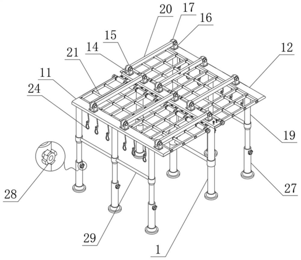
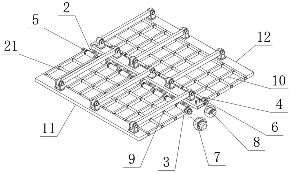
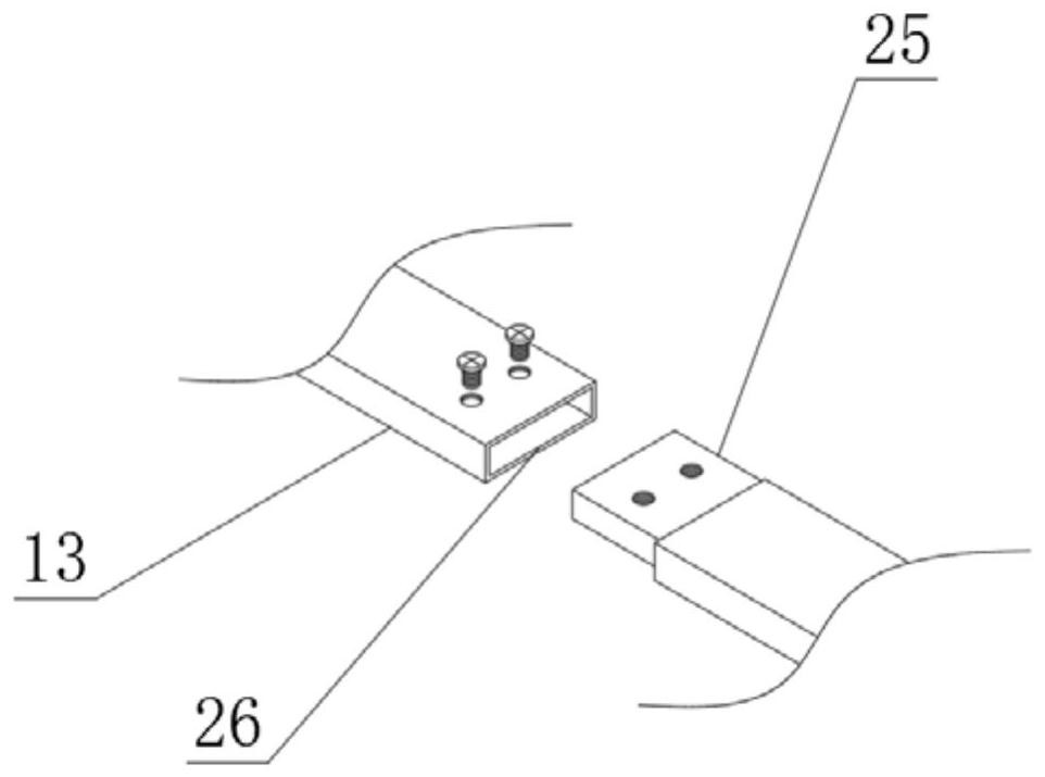
[0026] see Figure 1 to Figure 6 , the present invention provides a technical solution: an assembled top surface decorative truss structure, including a support rod 1, one end of the support rod 1 is fixedly connected to a main board 2, and one end of the main board 2 is fixedly connected to a first connecting pipe 3, the main board 2 The other end of the second connecting pipe 4 is fixedly connected with the second connecting pipe 4, the inside of the first connecting pipe 3 is fixedly connected with the first rotating rod 5, the inside of the second connecting pipe 4 is fixedly connected with the second rotating rod 6, and the inside of the first connecting pipe 5 i...


PUM


Abstract

The invention discloses an assembly type top surface decoration truss structure. The structure comprises supporting rods, a main plate, first joining pipes, second joining pipes, first rotating rods,second rotating rods and first rotating shafts, the surfaces of the second rotating rods are movably connected with the second rotating shafts, the surfaces of the first rotating shafts are movably connected with the first joining plates, the surfaces of the second rotating shafts are movably connected with second joining plates, and one ends of the first joining plates are fixedly connected withfirst limiting plates. The assembly type top surface decoration truss structure provides an assembly structure, and has the main advantages that during use, when the first joining plates and the second joining plates rotate, limiting rods can also rotate along with the first joining plates and the second joining plates, and due to the fact that the rotating angles of the limiting rods are limited,the rotating range of the first rotating shafts and the rotating range of the second rotating shafts can be limited, so that the rotating angle of the device is controlled within a reasonable range;and through the arrangement of inserting grooves and inserting blocks, and fixation of bolts, the same device can be connected.

Description

technical field [0001] The invention relates to the technical field of roof decoration equipment, in particular to an assembled roof decoration truss structure. Background technique [0002] A truss is a supporting beam structure composed of rods connected to each other with hinges at both ends by welding, riveting or bolts. The advantage of the truss is that the rods mainly bear tension or pressure, so that the strength of the material can be fully utilized. When the span is large, it can save material, reduce self-weight and increase rigidity compared with solid web beams. According to the structure, trusses can be divided into triangular trusses, trapezoidal trusses, polygonal trusses, vierendeel trusses and truss bridges. According to the product type, it can be divided into fixed truss, folding truss, butterfly truss and ball joint truss. From the perspective of mechanics, when the shape of the truss is similar to the bending moment diagram of a simply supported beam,...

Claims


Application Information

Patent Timeline
IPC IPC(8): E04B1/343E04B1/344E04B7/10E04B7/16
CPCE04B1/343E04B1/3431E04B1/3441E04B7/105E04B7/163
Inventor 何志伟俞旭光徐金虎赵越李广王文武郑强
Owner GOLD MANTIS FINE DECORATION TECH SUZHOU CO LTD
Why Eureka
Try Eureka