
High-precision quick-cooling crankshaft mold structure

A rapid cooling and high precision technology, applied in the field of crankshaft molds, can solve problems such as workpiece loss, poor preparation accuracy, and poor cooling efficiency

Pending Publication Date: 2021-01-29
MAANSHAN CHANGYE HEAVY IND TECH
View PDF0 Cites 1 Cited by
  • Summary
  • Abstract
  • Description
  • Claims
  • Application Information

AI Technical Summary

Problems solved by technology

[0006] The purpose of the present invention is to address the deficiencies of the prior art and provide a high-precision and fast-cooling crankshaft mold structure to solve the problems of poor preparation accuracy, easy to cause unnecessary loss of workpieces, and poor cooling efficiency proposed in the background art. , long preparation time and other issues

Method used


Image

  • High-precision quick-cooling crankshaft mold structure
  • High-precision quick-cooling crankshaft mold structure
  • High-precision quick-cooling crankshaft mold structure

Examples


Embodiment Construction

[0028] The following will clearly and completely describe the technical solutions in the embodiments of the present invention with reference to the accompanying drawings in the embodiments of the present invention. Obviously, the described embodiments are only some, not all, embodiments of the present invention. Based on the embodiments of the present invention, all other embodiments obtained by persons of ordinary skill in the art without making creative efforts belong to the protection scope of the present invention.

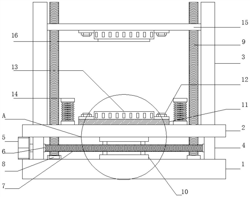
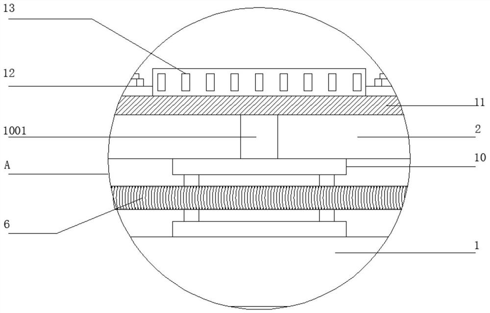
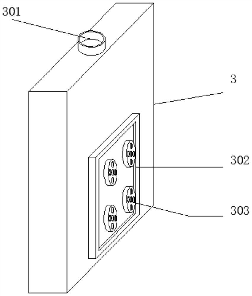
[0029] see Figure 1-4 , in the present embodiment: comprise base 1, base 1 upper end is provided with mounting plate 2, and mounting plate 2 upper end surface both sides is provided with side plate 3, is provided with support frame 4 between base 1 and mounting plate 2, and support frame 4- A motor 5 is arranged on the side, a turbine 6 is arranged in the support frame 4, bearings 8 are arranged at the bottom of both sides of the base 1, a threaded rod 9 is s...


PUM


Abstract

The invention discloses a high-precision quick-cooling crankshaft mold structure. The structure comprises a base; a mounting plate is arranged at the upper end of the base; side plates are arranged onthe two sides of the upper end surface of the mounting plate; a supporting frame is arranged between the base and the mounting plate; a motor is arranged on one side of the supporting frame; a turbine is arranged in the supporting frame; bearings are arranged at the bottoms of the two sides of the base; threaded rods are sleeved with the bearings; a hydraulic cylinder is arranged in the center ofthe base; a containing seat is arranged at the upper end of the mounting plate; a lower mold is arranged between two locking assemblies; buffer assemblies are arranged on the two sides of the mounting plate; a mounting frame is erected at the upper ends of the side plates; and an upper mold is arranged on the mounting frame through the locking assemblies. According to the high-precision quick-cooling crankshaft mold structure, the buffer assemblies and the hydraulic cylinder are arranged, so that the structure has the relatively-high preparation precision, and unnecessary waste of materials is avoided; and a spraying plate and a heat dissipation assembly are arranged, so that the structure has the good cooling efficiency, and the preparation time is greatly shortened.

Description

technical field [0001] The invention relates to the technical field of crankshaft molds, in particular to a high-precision and fast-cooling crankshaft mold structure. Background technique [0002] The crankshaft is the most important component in the engine. It bears the force transmitted by the connecting rod and converts it into torque through the crankshaft output and drives other accessories on the engine to work. The crankshaft is subjected to the joint action of the centrifugal force of the rotating mass, the periodically changing gas inertial force and the reciprocating inertial force, so that the crankshaft is subjected to the bending torsional load. Therefore require that the crankshaft has sufficient strength and rigidity, and the journal surface needs to be wear-resistant, work uniformly, and have good balance. Now a kind of high-precision crankshaft mold for preparing the crankshaft is needed. [0003] There are following defects or problems in the prior art: ...

Claims


Application Information

Patent Timeline
Patent Type & Authority Applications(China)
IPC IPC(8): B30B15/02B30B15/00B30B15/34
CPCB30B15/02B30B15/0076B30B15/34
Inventor 夏大亭程圣昌
Owner MAANSHAN CHANGYE HEAVY IND TECH
Learn More