Hard-tooth-surface gear machining process
A processing technology, hard tooth surface technology, applied in the field of hard tooth surface gear processing technology, can solve the problems of affecting the production efficiency of gears, low grinding efficiency, difficult to control the precision, etc., to improve the cylindricity accuracy of the inner hole and the tool life, Improve production efficiency and production benefits, and reduce the effect of cutting back
- Summary
- Abstract
- Description
- Claims
- Application Information
AI Technical Summary
Problems solved by technology
Method used
Image
Examples
Embodiment 1
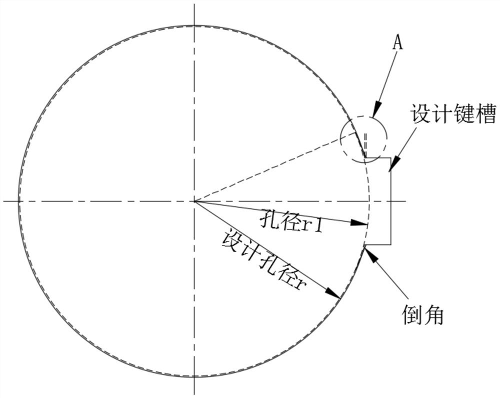
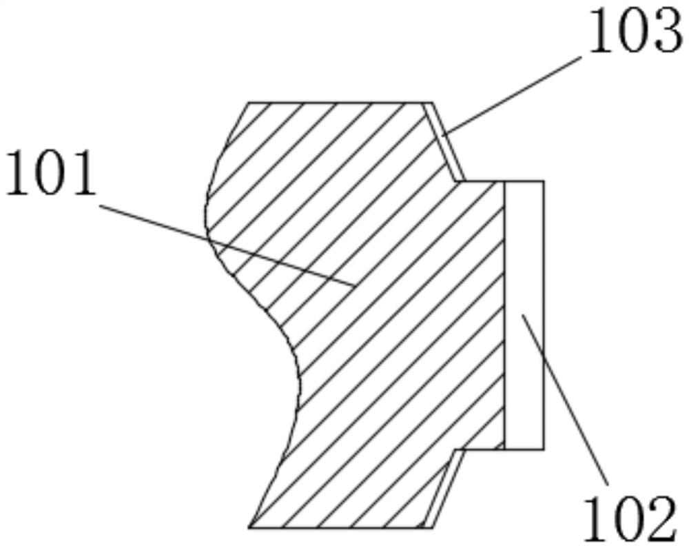
[0023] combined with Figure 1-7 The hard-toothed gear processing technology includes the following steps:
[0024] S1, blanking, making blank;
[0025] S2, rough turning, rough turning on the surface of the blank;
[0026] S3, quenching and tempering, performing quenching and tempering treatment on the blank;
[0027] S4, semi-finishing, semi-finishing the end face and outer wall of the blank;
[0028] S5. Process the inner hole, drill the inner hole at the center of the blank, determine the aperture r1 with a deformation allowance according to the deformation interval of the inner hole diameter before and after carburizing, and turn the inner hole diameter to r1;
[0029] In fact, it is clear to those skilled in the art that in actual operation, it is difficult to accurately control the interval value ∆r of the pore diameter change of the gear inner hole before and after carburizing, because it depends on the pore size, pore length, heat treatment temperature, time etc. ...
Embodiment 2
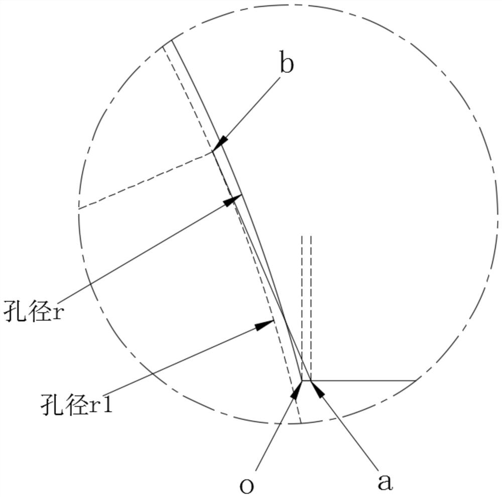
[0036] Compared with Example 1, in step S6, the distance value between the intersection point o and the end point a is based on the deformation interval before and after carburizing of the inner hole diameter, and the maximum deformation value ∆r is taken; the position of the end point a cannot be along the design The groove wall is randomly selected towards the inside of the keyway, that is, the structure of the keyway should not be too far behind, and the deformation error before and after carburizing should also be considered, so it should not be too far forward.
Embodiment 3
[0038] Compared with Example 1, in step S6, the chamfer is tangent to the circle where the aperture r1 is located at the tangent point b; that is, the chamfer is more gentle and excessive, and the buffering effect is maximized to reduce the gap of the intermittent turning notch. Back to eat the amount of knife.
PUM
 Abstract
Description
Claims
Application Information
 - Generate Ideas
- Intellectual Property
- Life Sciences
- Materials
- Tech Scout
- Unparalleled Data Quality
- Higher Quality Content
- 60% Fewer Hallucinations
Browse by: Latest US Patents, China's latest patents, Technical Efficacy Thesaurus, Application Domain, Technology Topic, Popular Technical Reports.
© 2025 PatSnap. All rights reserved.Legal|Privacy policy|Modern Slavery Act Transparency Statement|Sitemap|About US| Contact US: help@patsnap.com


