
Vanadium redox flow stack assembly process

An assembly process and liquid flow technology, which is applied in the direction of circuits, manufacturing tools, fuel cells, etc., can solve the problems of unstable quality and low production efficiency of vanadium liquid flow stack assembly process, and achieve good connection stability and not easy to be damaged Erosion, guarantee the effect of normal use

Inactive Publication Date: 2021-01-26
四川伟力得能源股份有限公司
View PDF3 Cites 0 Cited by
  • Summary
  • Abstract
  • Description
  • Claims
  • Application Information

AI Technical Summary

Problems solved by technology

[0003] The existing vanadium liquid flow stack assembly process has low production efficiency and unstable quality

Method used


Image

  • Vanadium redox flow stack assembly process
  • Vanadium redox flow stack assembly process
  • Vanadium redox flow stack assembly process

Examples


Embodiment Construction

[0046] In order to enable those skilled in the art to better understand the technical solutions of the present invention, the present invention will be further described in detail below in conjunction with specific embodiments.

[0047] The structure of stack a is as Figure 20 shown.

[0048] The invention provides a vanadium liquid flow stack assembly process, comprising the following steps:

[0049] S1 assembles the cell stack unit 1.

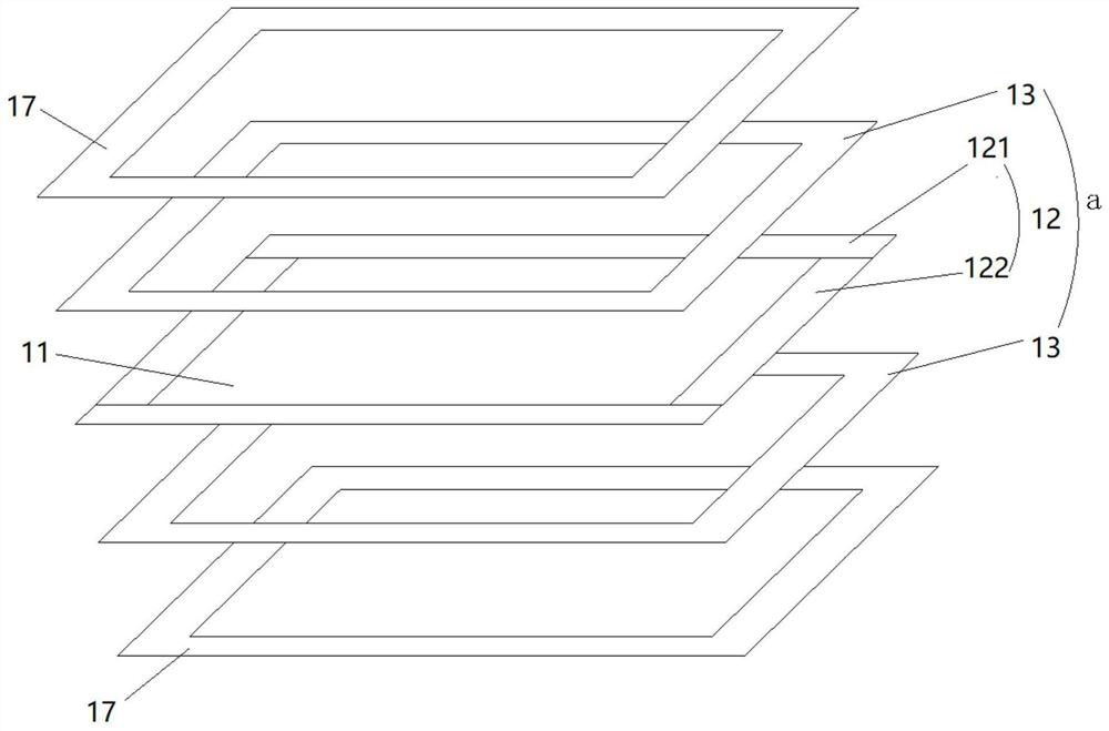
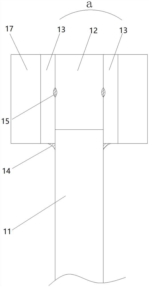
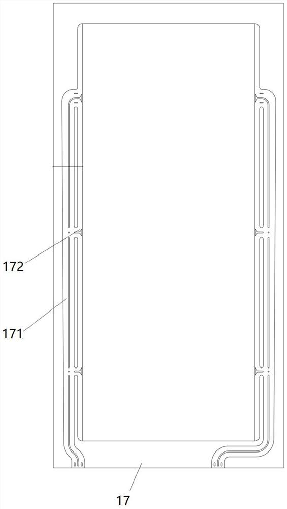
[0050] Such as Figure 1-5 As shown, the assembly steps of the battery unit mainly include:

[0051] A. Assembly of bipolar plate components:

[0052] A1, the insulating strip 1 121 and the insulating strip 2 122 are put together on the periphery of the entire edge area of ​​the bipolar plate 11 to form the insulating frame 12, and the edge of the hollow area in the middle of the insulating frame 12 is close to the periphery of the bipolar plate 11, that is , insulating strip one 121 and insulating strip two 122 are close to the bipolar...


PUM


Abstract

The invention discloses a vanadium liquid flow electric pile assembling process. The process comprises the following steps: S1, assembling an electric pile unit; S2, stacking a plurality of assembledelectric pile units into an electric pile, and then pressing the electric pile; S3, assembling a sealing plate; S4, assembling a confluence nozzle; and S5, assembling clamping plates on the top surface and the bottom surface of the stack. The stack units are assembled in a laser welding mode, stacked stacks are pressed through a stack press-fitting clamp, and finally a sealing plate and a confluence nozzle are assembled in a laser welding mode. By means of the steps, the vanadium liquid flow galvanic pile can be efficiently assembled, the assembled galvanic pile has no hidden danger of liquidleakage, the quality of the galvanic pile is greatly improved, and the service life of the galvanic pile is greatly prolonged.

Description

technical field [0001] The invention relates to a process for producing a vanadium liquid flow stack. Background technique [0002] Vanadium redox flow battery is a redox battery that uses vanadium as an active material in a circulating liquid state. The electrical energy of the vanadium battery is stored in the sulfuric acid electrolyte of vanadium ions in different valence states in the form of chemical energy, and the electrolysis is hydraulically injected into the battery stack through an external pump, and under the action of mechanical power, it is stored in different liquid storage tanks and half-cells. Circulating flow in a closed circuit, the proton exchange membrane is used as the diaphragm of the battery pack, the electrolyte solution flows through the electrode surface in parallel and an electrochemical reaction occurs, and the current is collected and conducted through the double electrode plate, thereby forming the mutual conversion of electrical energy and che...

Claims


Application Information

Patent Timeline
IPC IPC(8): H01M8/2404H01M8/18B23K26/21
CPCB23K26/21H01M8/188H01M8/2404Y02E60/50
Inventor 陈继军赵永贵唐钢
Owner 四川伟力得能源股份有限公司
Learn More