Imaging lens
An imaging lens and lens technology, applied in the field of imaging lens, can solve problems such as insufficient color and contrast, small range of working object distance, uneven picture definition, etc., to achieve small distortion, reduce burden ratio, and reduce tolerance sensitivity degree of effect
- Summary
- Abstract
- Description
- Claims
- Application Information
AI Technical Summary
Problems solved by technology
Method used
Image


Examples
Embodiment approach 1
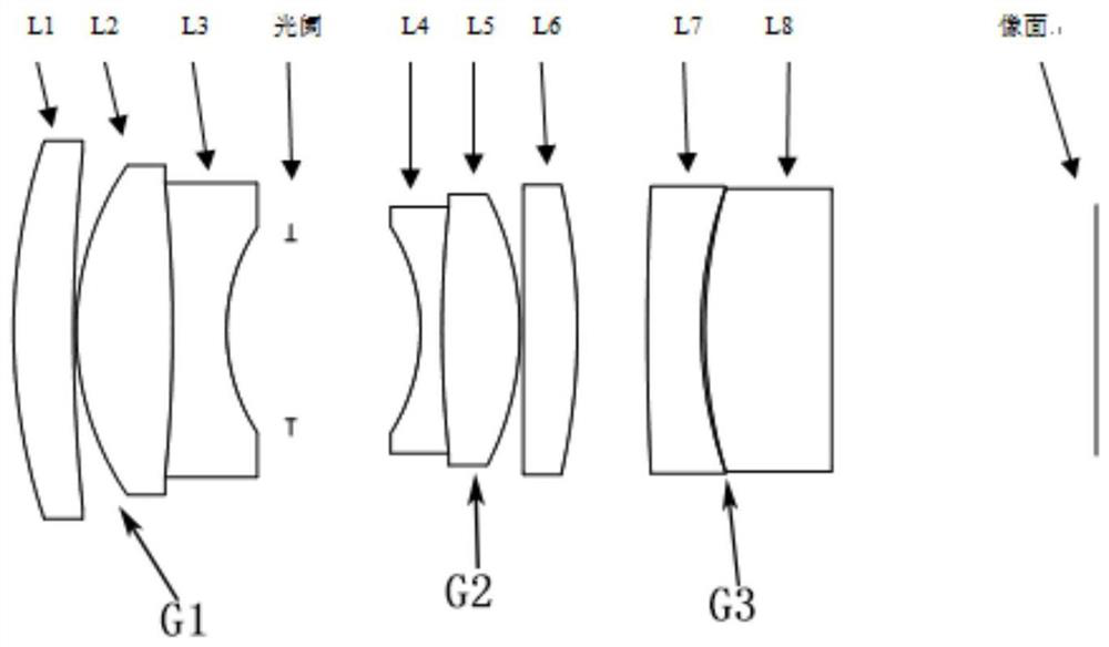
[0073] figure 1 is a schematic diagram showing the structure of the imaging lens according to Embodiment 1 of the present invention.
[0074] In Embodiment 1, the total length of the optical system is TTL=42.9mm, the focal length of the system is f=25.1mm, the imaging object distance range of the system is 0.15m~inf, the frame size of the system is Y=12mm, and the F-number FNO=3.1.
[0075] The following table 2 lists the relevant parameters of each lens of the present embodiment, including surface type, radius of curvature, thickness, refractive index of material, Abbe number:
[0076] Face number surface type R value thickness Refractive index Abbe number sur1 standard 20.54 2.35 1.85 52.35 sur2 standard 52.41 0.5 sur3 standard 8.45 2.95 1.6 68.0 sur4 standard 25.71 1.2 1.58 46.17 sur5 standard 6.88 5.57 stop standard infinity 3.15 Sur7 standard -8.84 0.8 1.68 33.85 S...
Embodiment approach 2
[0081] Figure 6 is a schematic diagram showing the structure of the imaging lens according to Embodiment 2 of the present invention.
[0082] In Embodiment 2, the total length of the optical system is TTL=43.5mm, the focal length of the system is f=26.4mm, the imaging object distance range of the system is 0.15m-inf, the frame size of the system is Y=12.5mm, and the F-number FNO=2.5.
[0083] The following table 3 lists the relevant parameters of each lens of this embodiment, including surface type, radius of curvature, thickness, refractive index of material, Abbe number:
[0084] Face number surface type R value thickness Refractive index Abbe number sur1 standard 22.5 2.45 1.78 60.23 sur2 standard 64.2 0.15 sur3 standard 10.73 3.56 1.55 75.0 sur4 standard -54.07 2.0 1.58 49.2 sur5 standard 8.83 2.38 stop standard infinity 4.80 Sur7 standard -10.24 1.2 1.65 33.84 Sur...
Embodiment approach 3
[0089] Figure 11 is a schematic diagram showing the structure of the imaging lens according to Embodiment 3 of the present invention.
[0090] In Embodiment 3, the total length of the optical system is TTL=53.00mm, the focal length of the system is f=33.5mm, the imaging object distance range of the system is 0.15m~inf, the frame size of the system is Y=11.5mm, and the F-number FNO=2.6.
[0091] The following table 4 lists the relevant parameters of each lens of this embodiment, including surface type, radius of curvature, thickness, refractive index of material, Abbe number:
[0092] Face number surface type R value thickness Refractive index Abbe number sur1 standard 35.02 4.2 1.85 37.5 sur2 standard 165.14 0.2 sur3 standard 18.2 4.1 1.50 80.2 sur4 standard infinity 3.85 1.70 35.15 sur5 standard 13.5 4.89 stop standard infinity 4.5 Sur7 standard -15.75 2.54 1.62 36.35 ...
PUM
 Abstract
Description
Claims
Application Information
 - R&D
- Intellectual Property
- Life Sciences
- Materials
- Tech Scout
- Unparalleled Data Quality
- Higher Quality Content
- 60% Fewer Hallucinations
Browse by: Latest US Patents, China's latest patents, Technical Efficacy Thesaurus, Application Domain, Technology Topic, Popular Technical Reports.
© 2025 PatSnap. All rights reserved.Legal|Privacy policy|Modern Slavery Act Transparency Statement|Sitemap|About US| Contact US: help@patsnap.com