
Biogas slurry purification device and purification method

A technology of purification device and biogas slurry, which is applied in the direction of biochemical cleaning device, biochemical equipment and method, sterilization method, etc., can solve the problem of reducing the amount of feed, affecting the gas production rate of dry matter in the anaerobic fermentation system, and affecting Methane bacteria activity and other issues

Pending Publication Date: 2021-01-26
深圳市德润生物质投资有限公司
View PDF0 Cites 3 Cited by
  • Summary
  • Abstract
  • Description
  • Claims
  • Application Information

AI Technical Summary

Problems solved by technology

[0003] However, the following problems exist in the biogas slurry reflux in my country's current biogas projects: 1. The accumulation of ash and refractory substances in the biogas slurry leads to an increasingly high concentration of the biogas slurry, and the reflux of the biogas slurry with a high solid content will lead to a decrease in the amount of feed and affect the biogas slurry. Liquid engineering gas production
2. The concentration of biogas slurry is high, the reflux time of biogas slurry is long, and the accumulation of gas production inhibitors is too much, which affects the activity of methane bacteria, thus affecting the stability of anaerobic fermentation system and the gas production rate of dry matter of materials
3. Long reflux time leads to the accumulation of viscous substances such as lignin in the biogas slurry, and the viscosity of the biogas slurry increases, which leads to foaming in the fermentation tank of the biogas project, which affects the normal operation of the biogas project and the subsequent treatment of biogas

Method used


Image

  • Biogas slurry purification device and purification method

Examples


Embodiment Construction

[0025] The technical solutions of the present invention will be clearly and completely described below in conjunction with the accompanying drawings. Apparently, the described embodiments are some of the embodiments of the present invention, but not all of them. Based on the embodiments of the present invention, all other embodiments obtained by persons of ordinary skill in the art without making creative efforts belong to the protection scope of the present invention.

[0026] In the description of the present invention, it should be noted that the orientation or positional relationship indicated by the terms "front", "upper", "lower", "left", "right", "vertical", "horizontal" etc. are based on The orientation or positional relationship shown in the drawings is only for the convenience of describing the present invention and simplifying the description, and does not indicate or imply that the referred device or element must have a specific orientation, be constructed and opera...


PUM


Abstract

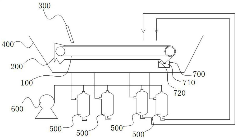
The invention provides a biogas slurry purification device and purification method, and relates to the technical field of biogas slurry treatment in biogas engineering. The biogas slurry purificationdevice comprises an aeration device, wherein the aeration device comprises a tank body and a fan arranged at the lower part in the tank body, biogas slurry flows into the tank body, and the fan generates flowing gas to intermittently aerate the biogas slurry. A filtering device comprises a conveying belt and filtering cloth which is wound on the surface of the conveying belt and moves along with the conveying belt, a slurry feeding pipe is arranged above the front end of the conveying belt, and a hopper for recycling filtered biogas slurry is arranged below the conveying belt. Biogas slurry aerated by the aeration device flows onto the filtering cloth through the feeding pipe, the biogas slurry flows into the hopper through the filtering cloth, filter residues move backwards along with thefiltering cloth, and the filtering device is located in a vacuum environment. According to the biogas slurry purification device and purification method provided by the invention, the content of aerobic pollutants is reduced through aeration, solid particles are filtered, the viscosity of biogas slurry is reduced, and the gas production rate is increased.

Description

technical field [0001] The invention relates to the technical field of biogas slurry treatment, in particular to a biogas slurry purification device and a purification method. Background technique [0002] At present, as the country gradually pays attention to the harmless and resource utilization of agricultural and forestry waste (straw, livestock and poultry manure, etc.), the biogas anaerobic fermentation project is ushering in a period of rapid development. During the implementation of biogas projects, biogas slurry backflow, as a common method, can reduce the discharge of biogas slurry, and can also promote the accumulation of beneficial elements and maintain an appropriate carbon-nitrogen ratio. [0003] However, the following problems exist in the biogas slurry reflux in my country's current biogas projects: 1. The accumulation of ash and refractory substances in the biogas slurry leads to an increasingly high concentration of the biogas slurry, and the reflux of the...

Claims


Application Information

Patent Timeline
Patent Type & Authority Applications(China)
IPC IPC(8): C12M1/107C12M1/12C12M1/04C12M1/00C12P5/02C02F11/04
CPCC02F11/04C12M21/04C12M29/04C12M29/06C12M29/18C12M29/26C12M33/14C12M33/20C12P5/023Y02E50/30
Inventor 胡凯付伟张海平张博
Owner 深圳市德润生物质投资有限公司
Learn More