
Punching device with up-down shaking function for building construction

A technology for building construction and drilling devices, which can be used in driving devices, feeding devices, manufacturing tools, etc., and can solve time-consuming and labor-intensive problems

Inactive Publication Date: 2021-01-26
张莹
View PDF0 Cites 0 Cited by
  • Summary
  • Abstract
  • Description
  • Claims
  • Application Information

AI Technical Summary

Problems solved by technology

[0002] Drilling machine refers to the general name of machinery and equipment that leaves cylindrical holes or holes on the target by means of rotary cutting or rotary extrusion with a tool that is harder and sharper than the target. Machines, drilling machines, through-hole machines, etc., achieve the desired effect by drilling precision parts. Drilling machines include semi-automatic drilling machines and fully automatic drilling machines. With the increase in human resource costs, most enterprises Fully automatic drilling machines are considered as the development direction; the existing drilling devices have certain disadvantages in use, and secondly, the existing drilling devices are basically semi-braking drilling devices when punching holes, all of which are manual Move the drilling machine, and during the drilling process, every time the hole is drilled to a certain depth, it needs to be retracted, so that the drilling waste can exit from the cavity, so as to drill deeper, but these are semi-braking for manual operation. Time-consuming and labor-intensive

Method used


Image

  • Punching device with up-down shaking function for building construction
  • Punching device with up-down shaking function for building construction
  • Punching device with up-down shaking function for building construction

Examples


Embodiment Construction

[0023] The following will clearly and completely describe the technical solutions in the embodiments of the present invention with reference to the accompanying drawings in the embodiments of the present invention. Obviously, the described embodiments are only some, not all, embodiments of the present invention. Based on the embodiments of the present invention, all other embodiments obtained by persons of ordinary skill in the art without making creative efforts belong to the protection scope of the present invention.

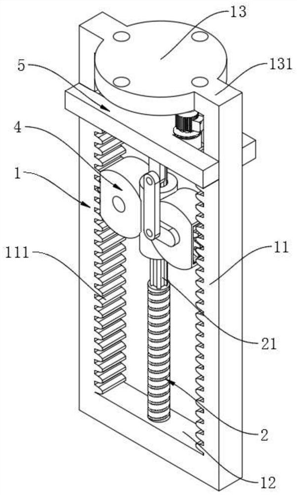
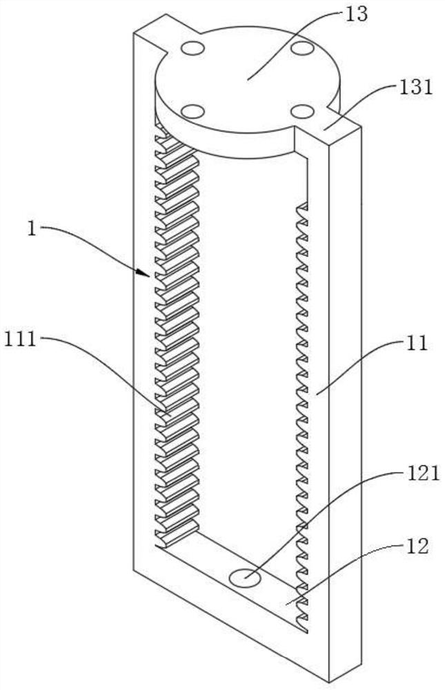
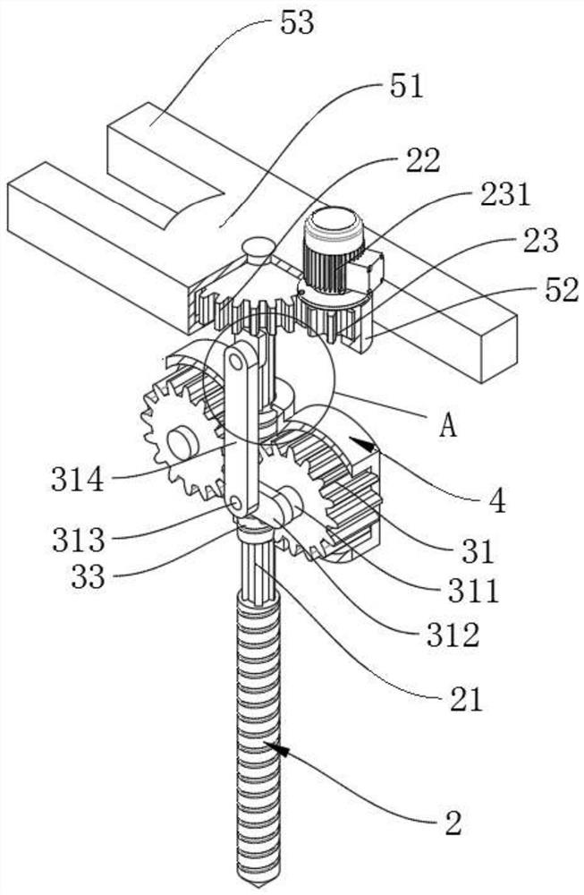
[0024] see Figure 1~5 , in an embodiment of the present invention, a punching device with a function of shaking up and down for building construction, including a frame 1, the frame 1 includes two parallel and vertical racks 11, the inner side of the rack 11 is fixed with several The inner teeth 111 are arranged in a linear and equidistant manner. The inner sides of the bottom ends of the two vertical racks 11 are fixedly connected with a fixed connecting rod...


PUM


Abstract

The invention discloses a punching device with an up-down shaking function for building construction. The punching device comprises a frame. The frame comprises two vertical racks which are parallel to each other. A plurality of inner teeth which are linearly arranged at equal intervals are fixedly arranged on the inner side of each rack, a fixed connecting rod is fixedly connected to the inner sides of the bottom ends of the two vertical racks, and a through hole runs through the fixed connecting rod. According to the punching device, a motor output shaft rotates to drive a small gear to rotate, and the small gear drives a large gear to rotate, rotation of a punching shaft is achieved, so that the drilling effect is achieved; and a first gear and a second gear are arranged to rotate on arack, the punching shaft, a lifting shaking device and a second limiting piece are driven to do reciprocating motions in the vertical direction of the frame, an arranged eccentric connecting rod rotates with a first rotating shaft as the axis, the punching shaft and the second limiting piece are pulled by the eccentric connecting rod to do reciprocating shaking in the vertical direction, and the punching shaft retreats from a hole during punching, so that the effect of discharging scraps in the hole is achieved, and the problems in the background technology are solved.

Description

technical field [0001] The invention relates to the technical field of building construction, in particular to a drilling device with a vertical shaking function for building construction. Background technique [0002] Drilling machine refers to the general name of machinery and equipment that leaves cylindrical holes or holes on the target by means of rotary cutting or rotary extrusion with a tool that is harder and sharper than the target. Machines, drilling machines, through-hole machines, etc., achieve the desired effect by drilling precision parts. Drilling machines include semi-automatic drilling machines and fully automatic drilling machines. With the increase in human resource costs, most enterprises Fully automatic drilling machines are considered as the development direction; the existing drilling devices have certain disadvantages in use, and secondly, the existing drilling devices are basically semi-braking drilling devices when punching holes, all of which are m...

Claims


Application Information

Patent Timeline
Patent Type & Authority Applications(China)
IPC IPC(8): B23B47/06B23B47/20B23Q11/00
CPCB23Q5/10B23Q5/28B23Q11/0042
Inventor 张莹
Owner 张莹
Learn More