Connectors and Cable Harnesses

A technology of connectors and cables, which is applied in the direction of connection, two-part connection device, parts of connection device, etc., and can solve problems such as maintenance

Active Publication Date: 2022-01-04
JAPAN AVIATION ELECTRONICS IND LTD
View PDF8 Cites 0 Cited by
  • Summary
  • Abstract
  • Description
  • Claims
  • Application Information

AI Technical Summary

Problems solved by technology

[0004] In Patent Document 1, there is still room for improvement in terms of holding the cable so as not to pull the cable out of the connector

Method used


Image

  • Connectors and Cable Harnesses
  • Connectors and Cable Harnesses
  • Connectors and Cable Harnesses

Examples


Embodiment Construction

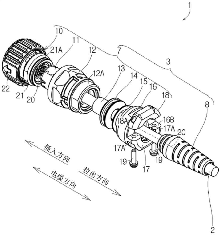
[0096] Below for the embodiment of the present invention, refer to Figure 1 to Figure 7 Be explained.

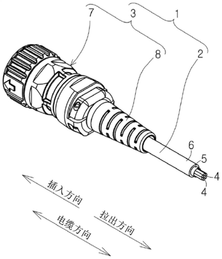
[0097] figure 1 Indicates cable harness 1. Such as figure 1 As shown, the cable harness 1 includes a multi-core cable 2 (cable) and a multi-core connector 3 (connector) installed at the end of the multi-core cable 2 .

[0098] The multi-core cable 2 is formed by covering a plurality of coated electric wires 4 with a braid 5 and a sheath 6 . That is, the braid 5 accommodates a plurality of coated electric wires 4 , and the sheath 6 accommodates a plurality of coated electric wires 4 and the braid 5 . The sheath 6 is, for example, made of polyvinyl chloride, polyethylene, or Teflon (registered trademark).

[0099] Herein, refer to figure 1 Define the direction of the cable, the direction of insertion, and the direction of extraction. The cable direction is the length direction of the multi-core cable 2 . The direction of the cable includes the direction of insertio...


PUM


Abstract

The strain relief 8 includes a cylindrical relief main body 32 , an outer convex portion 33 and an inner convex portion 34 . The connector main bodies 7 are arranged to face each other with the canceller main body 32 interposed therebetween, and include the saddle connecting portion 17 and the clamping saddle 18 which can clamp the canceller main body 32 . The saddle connecting portion 17 and the clamping saddle 18 are configured such that the canceller main body 32 can be elastically deformed radially inwardly in a state where the canceller main body 32 is clamped. A compression nut-side inner concave portion 40 and a saddle-side inner concave portion 35 are respectively formed on the saddle connection portion 17 and the clamping saddle 18, and the compression nut-side inner concave portion 40 and the saddle-side inner concave portion 35 are both aligned in the circumferential direction. Extending in an arc shape, it is used to accommodate the outer convex portion 33 of the strain relief member 8 .

Description

technical field [0001] The invention relates to a connector and a cable harness. Background technique [0002] Such as Figure 10 As shown, JPH01-502365A (Patent Document 1) discloses a bidirectional optical fiber connector 103, which includes a base 100, a bushing 101 and a bending limiting member 102 made of hard plastic material. [0003] The base 100 is formed with a first cavity 105 for accommodating the flange 104 of the bushing 101 and a second cavity 107 for accommodating the flange 106 of the bending limiter 102 . [0004] In Patent Document 1, there is still room for improvement in terms of holding the cable so as not to pull the cable out of the connector. Contents of the invention [0005] The problem to be solved by the invention [0006] An object of the present invention is to provide a technique for improving the holding force of cables. [0007] means to solve the problem [0008] According to the viewpoint of the present invention, the present invent...

Claims


Application Information

Patent Timeline
Patent Type & Authority Patents(China)
IPC IPC(8): H01R13/56H01R13/58H01R24/00
CPCH01R13/5812H01R13/562H01R24/00
Inventor 铃木智幸
Owner JAPAN AVIATION ELECTRONICS IND LTD
Why Eureka
Try Eureka