A transmission structure of an electric push rod

A transmission structure, electric push rod technology, applied in the direction of electric components, transmission devices, gear transmission devices, etc., can solve the problems of reduced service life of electric push rods, shaking of rotating shafts, and large wear, etc., to extend service life and reduce The effect of transmission wear and improvement of supporting force

Active Publication Date: 2022-04-05
浙江力耐得传动科技有限公司
View PDF8 Cites 0 Cited by
  • Summary
  • Abstract
  • Description
  • Claims
  • Application Information

AI Technical Summary

Problems solved by technology

[0004] However, in the process of installation and use, it is often necessary to disassemble the electric push rod and the motor for maintenance or to add lubricating oil, and in this process, the output shaft of the motor will inevitably contact and collide with one end of the rotating shaft, making the rotating shaft The impact force in the direction perpendicular to its axial direction causes the rotating shaft to shake in the radial direction. At this time, there is a gap between the screw and the screw during transmission, and the wear is large during transmission, and the service life of the electric push rod is greatly reduced.

Method used


Image

  • A transmission structure of an electric push rod
  • A transmission structure of an electric push rod
  • A transmission structure of an electric push rod

Examples


Embodiment Construction

[0035] The present invention will be further described in detail below with reference to the accompanying drawings.

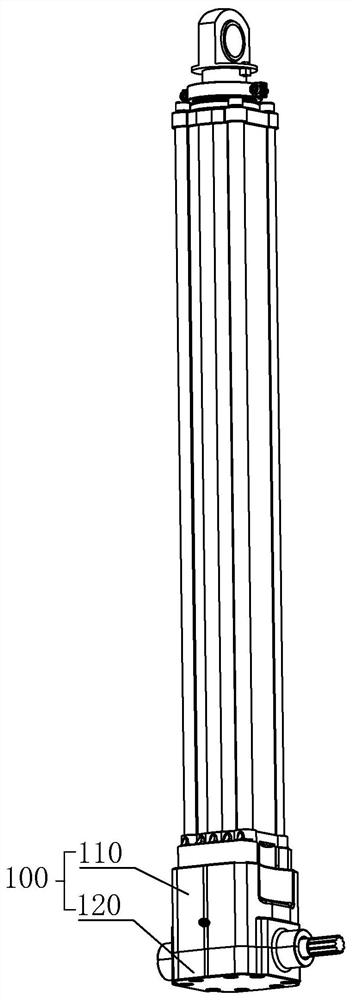
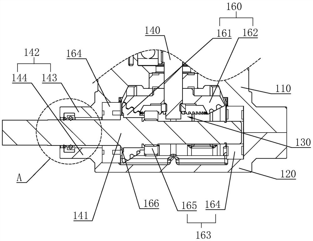
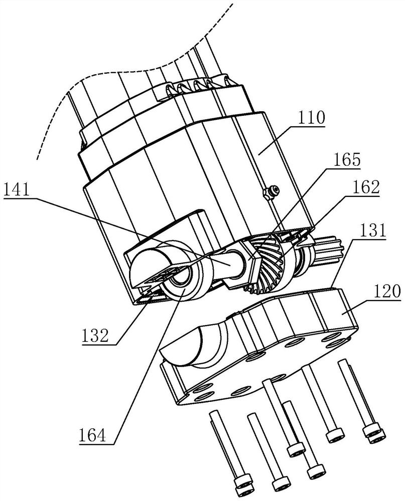
[0036] A transmission structure of an electric push rod, refer to figure 1 , figure 2 , image 3 , including a transmission case 100 composed of a front cover 110 and a rear cover 120, a receiving cavity 130 is formed in the transmission case 100, a positioning part 131 is integrally provided on the inner wall of the rear cover 120, and a positioning part 131 is embedded on the inner wall of the front cover 110. Position the insert groove 132 . When the rear cover 120 and the front cover 110 are closed together, the positioning portion 131 will be inserted into the positioning groove 132 and fixed by bolts.

[0037] refer to image 3 , Figure 4 , the front cover 110 is rotatably connected with a lead screw 140, the transmission casing 100 is rotatably connected with a rotating shaft 141 perpendicular to the lead screw 140, one end of the rotating shaft 1...


PUM


Abstract

The present invention relates to the technical field of electric push rods, and relates to a transmission structure of electric push rods, which includes a transmission case composed of a front cover and a rear cover, and an accommodation cavity is formed in the transmission case, and is characterized in that: A screw rod is connected in rotation, and a rotating shaft perpendicular to the screw rod is connected in rotation on the transmission housing. One end of the rotating shaft protrudes from the transmission housing, and the rotating shaft and the screw rod are linked through a deceleration bevel gear set. The outer wall of the transmission housing is provided with a reinforcing support sleeved on the rotating shaft. The invention has the following effects: the reinforcing support is arranged on the outer wall of the transmission case, which can increase its supporting force and reduce the possibility of the rotating shaft shifting in the radial direction, so that when the rotating shaft drives the screw to rotate through the deceleration bevel gear set , Reduce transmission wear, thereby prolonging the service life of the electric push rod.

Description

technical field [0001] The invention relates to the technical field of electric push rods, in particular to a transmission structure of electric push rods. Background technique [0002] Electric push rod is an electric drive device that converts the rotary motion of the motor into the linear reciprocating motion of the push rod. It can be used as an executive machine in various simple or complex technological processes to realize remote control, centralized control or automatic control. It has been widely used in various electromechanical complete sets of equipment and its automatic control devices because of its advantages of good stability, high running accuracy and fast response speed. [0003] Generally, a screw rod is arranged on the electric push rod along its length direction, and a rotating shaft for driving the screw rod to rotate will be set at the lower end of the electric push rod. One end of the rotating shaft will extend out of the electric push rod, and the ou...

Claims


Application Information

Patent Timeline
Patent Type & Authority Patents(China)
IPC IPC(8): F16H1/14F16H57/029F16H57/021F16H57/04H02K7/06H02K7/116
CPCF16H1/14F16H57/029F16H57/021F16H57/04H02K7/06H02K7/116F16H2057/02034
Inventor 倪建芬
Owner 浙江力耐得传动科技有限公司
Why Eureka
Try Eureka