
Differential input circuit, control method thereof and differential amplifier

A differential input circuit, differential input technology, applied in differential amplifiers, amplifiers, amplifiers with semiconductor devices/discharge tubes, etc., can solve problems such as reducing the accuracy of differential amplifiers, differential amplifier offset voltage, and asymmetric device characteristics

Active Publication Date: 2021-01-19
江阴圣邦微电子制造有限公司
View PDF8 Cites 1 Cited by
  • Summary
  • Abstract
  • Description
  • Claims
  • Application Information

AI Technical Summary

Problems solved by technology

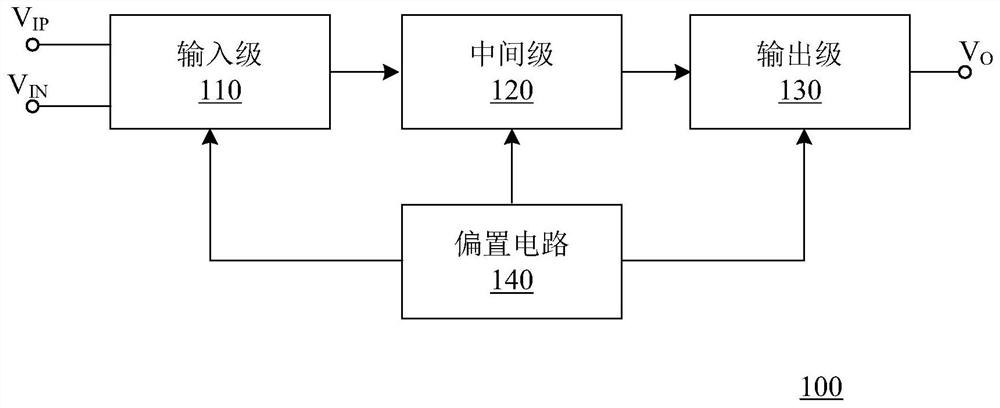
However, when the input of the existing differential amplifier is a large differential signal, the transistor pair in the differential input circuit 110 works in a bias state for a long time, and the asymmetric operation of the transistor pair for a long time will cause the transistor pair in the differential input circuit to be biased. The asymmetry of the device characteristics causes the differential amplifier to generate an offset voltage and reduces the accuracy of the differential amplifier

Method used


Image

  • Differential input circuit, control method thereof and differential amplifier
  • Differential input circuit, control method thereof and differential amplifier
  • Differential input circuit, control method thereof and differential amplifier

Examples


Embodiment Construction

[0032] Hereinafter, the present invention will be described in more detail with reference to the accompanying drawings. In the various figures, identical elements are indicated with similar reference numerals. For the sake of clarity, various parts in the drawings have not been drawn to scale. Also, some well-known parts may not be shown in the drawings.

[0033] In the following, many specific details of the present invention, such as structures, materials, dimensions, processes and techniques of components, are described for a clearer understanding of the present invention. However, the invention may be practiced without these specific details, as will be understood by those skilled in the art.

[0034] It should be understood that in the following description, a "circuit" refers to a conductive loop formed by at least one element or sub-circuit through electrical or electromagnetic connections. When an element or circuit is said to be "connected to" another element or an...


PUM


Abstract

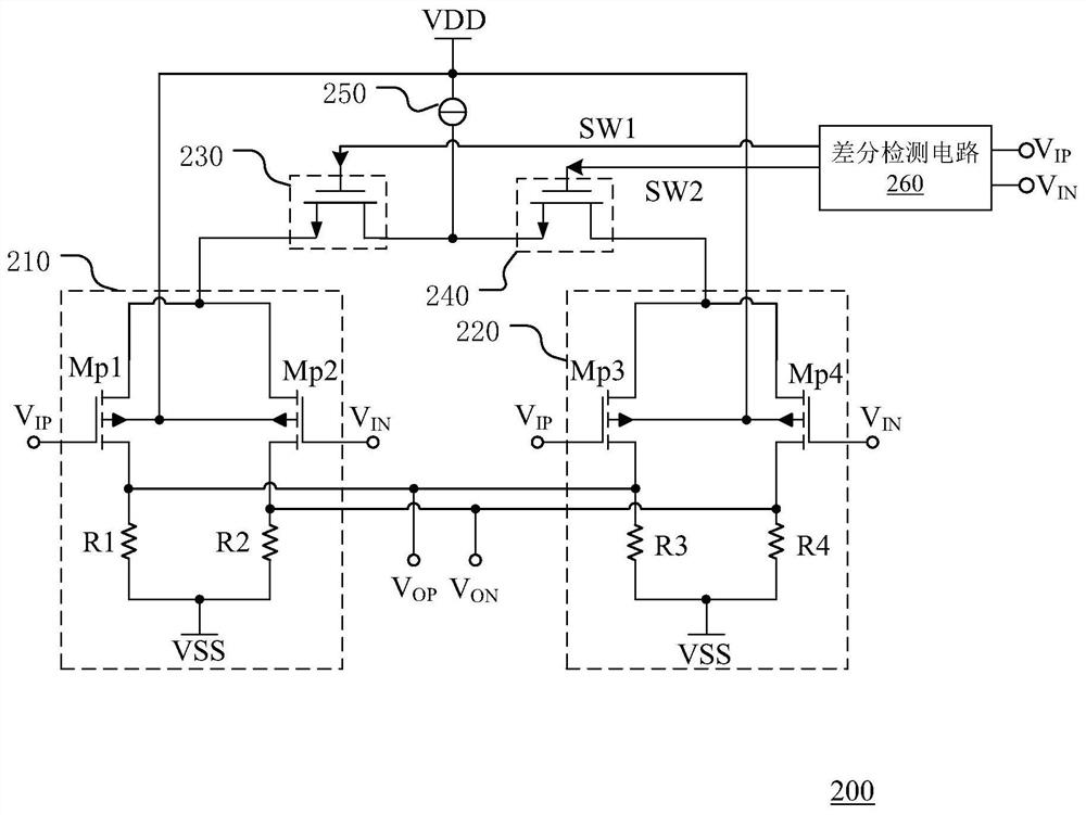
The invention discloses a differential input circuit, a control method of the differential input circuit, and a differential amplifier. The differential input circuit comprises: a first differential input stage connected in series with a first switch between a positive power supply terminal and a negative power supply terminal; a second differential input stage, wherein the second differential input stage and the second switch are connected in series between the positive power supply end and the negative power supply end; a differential detection circuit which is used for conducting one of thefirst switch and the second switch according to a first input signal and a second input signal, wherein the positive input ends of the first differential input stage and the second differential inputstage receive the first input signal, the negative input ends of the first differential input stage and the second differential input stage receive the second input signal, the size of the differential transistor pair in the first differential input stage is different from the size of the differential transistor pair in the second differential input stage, so that increase of input offset voltagecaused by asymmetry of the transistor pair of the single input stage under long-time large differential signal work can be prevented, and the precision of the amplifier is further prevented from being influenced.

Description

technical field [0001] The invention relates to the technical field of integrated circuit testing, and in particular to a differential input circuit, a control method thereof and a differential amplifier including the differential input circuit. Background technique [0002] A differential amplifier is a circuit that can amplify the difference between two input voltages, also known as a differential amplifier. figure 1 A schematic diagram showing the structure of an existing differential amplifier, such as figure 1 As shown, the differential amplifier 100 includes a differential input circuit 110 , an intermediate stage circuit 120 , an output stage circuit 130 and a bias circuit 140 . The differential input circuit 110 is also called a pre-stage circuit, which is generally a high-performance differential amplifier circuit with double-terminal input, and its input terminal is used to input a pair of differential signals. The intermediate stage circuit 120 is the main ampli...

Claims


Application Information

Patent Timeline
IPC IPC(8): H03F3/45
CPCH03F3/45376
Inventor 孙德臣
Owner 江阴圣邦微电子制造有限公司
Learn More