
Steel plate spraying machine capable of utilizing static electricity and achieving automatic spraying

A technology of automatic spraying and spraying machine, which is applied in the direction of friction discharge spraying, spraying device with movable outlet, spraying device, etc. It can solve the problems of paint waste, manual spraying, time-consuming and laborious, etc., and achieve the effect of improving spraying effect and reducing waste

Inactive Publication Date: 2021-01-19
温州根旭电子科技有限公司
View PDF0 Cites 1 Cited by
  • Summary
  • Abstract
  • Description
  • Claims
  • Application Information

AI Technical Summary

Problems solved by technology

[0002] In our daily life, static electricity will always be generated, and static electricity is a relatively common physical phenomenon in nature. Its essence is a static charge. When the workpiece is spraying, the paint is atomized due to the pressure of the spray gun, and then Applied on the surface of the object to be coated, the process will lead to waste of paint and affect the health of the staff
The existing spraying process usually uses a spray gun or an atomizer to spray directly, which leads to waste of paint and affects the health of workers. Some spraying machines that use static electricity for spraying require manual spraying, which is time-consuming and laborious. A method that can use static electricity and automatically spray The steel plate spraying machine can solve the above problems

Method used


Image

  • Steel plate spraying machine capable of utilizing static electricity and achieving automatic spraying
  • Steel plate spraying machine capable of utilizing static electricity and achieving automatic spraying
  • Steel plate spraying machine capable of utilizing static electricity and achieving automatic spraying

Examples


Embodiment Construction

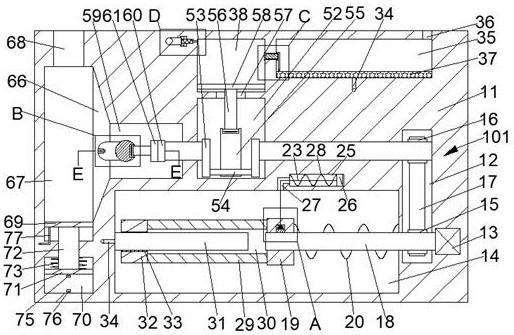
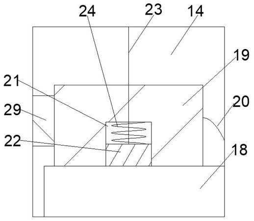
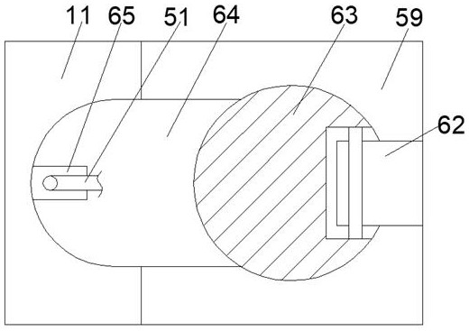
[0019] Combine below Figure 1-6 The present invention is described in detail, wherein, for the convenience of description, the orientations mentioned below are defined as follows: figure 1 The up, down, left, right, front and back directions of the projection relationship itself are the same.

[0020] A steel plate spraying machine capable of using static electricity and automatic spraying according to the present invention includes a spraying body 11, a belt chamber 12 is provided in the spraying body 11, and a linkage device 101 is provided in the belt chamber 12, so The left wall of the belt chamber 12 is fixed with a power motor 13, the power of the linkage device 101 comes from the power motor 13, the left side of the belt chamber 12 is provided with a friction chamber 14, and the left end face of the power motor 13 is connected to There is a screw rod 18, and the left end surface of the screw rod 18 runs through the belt cavity 12 and extends into the friction cavity 1...


PUM


Abstract

The invention discloses a steel plate spraying machine capable of utilizing static electricity and achieving automatic spraying. The machine comprises a spraying machine body, wherein a belt cavity isformed in the spraying machine body, a linkage device is arranged in the belt cavity, a power motor is fixedly arranged in the left wall of the belt cavity, and power of the linkage device comes fromthe power motor. A friction cavity is formed in the left side of the belt cavity, the left end face of the power motor is in power connection with a lead screw, the left end face of the lead screw penetrates through the belt cavity and extends into the friction cavity, and a transversely-moving sliding block capable of sliding left and right is arranged in the friction cavity. The manner that furrubs with a rubber rod, and then the rubber rod carries negative electricity is utilized, firstly, electrons carried by the rubber rod are transmitted to paint, then the paint carrying the electronsis sprayed to a grounded steel plate through a spray head, due to the fact that the steel plate is grounded, the electric potential energy of the steel plate is zero, then the paint can be effectivelysprayed to the surface of the steel plate, waste is reduced, meanwhile, the spray head can swing, and the spraying effect is improved.

Description

technical field [0001] The invention relates to the technical field related to static electricity, in particular to a steel plate spraying machine capable of using static electricity and automatically spraying. Background technique [0002] In our daily life, static electricity will always be generated, and static electricity is a relatively common physical phenomenon in nature. Its essence is a static charge. When the workpiece is spraying, the paint is atomized due to the pressure of the spray gun, and then Applying to the surface of the object to be coated will lead to waste of paint and affect the health of the staff. The existing spraying process usually uses a spray gun or an atomizer to spray directly, which leads to waste of paint and affects the health of workers. Some spraying machines that use static electricity for spraying require manual spraying, which is time-consuming and laborious. A method that can use static electricity and automatically spray The advance...

Claims


Application Information

Patent Timeline
IPC IPC(8): B05B5/047B05B3/14
CPCB05B3/14B05B5/047
Inventor 赵国庆
Owner 温州根旭电子科技有限公司
Learn More