Air conditioner

A technology for air-conditioning units and heat media, which is used in transportation and packaging, air handling equipment, space heating and ventilation, etc., and can solve problems such as limiting refrigerant discharge capacity, inability to cope with changes in supply air temperature, and increased power consumption.

Active Publication Date: 2021-01-15
DENSO CORP
View PDF4 Cites 0 Cited by
  • Summary
  • Abstract
  • Description
  • Claims
  • Application Information

AI Technical Summary

Problems solved by technology

[0010] Here, in the vehicle air conditioner described in Patent Document 1, the compressor of the refrigeration cycle device limits the refrigerant discharge capacity from the viewpoint of noise and the like. , whose capabilities are changed according to the situation
In this case, if the capacity of the compressor fluctuates, the temperature of the supply air may fluctuate due to the inability to cope with the capacity fluctuation of the compressor in the auxiliary electric heater mode.
[0011] In addition, as a result of the change in capacity of the compressor, the electric heater becomes the main heating source, which increases the power consumption during heating.

Method used


Image

  • Air conditioner
  • Air conditioner
  • Air conditioner

Examples


no. 1 approach

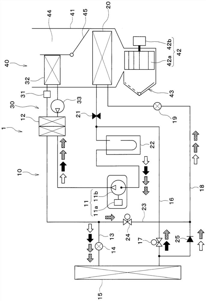
[0034] according to Figure 1 to Figure 6 A first embodiment of the present invention will be described. figure 1 It is a schematic configuration diagram of the vehicle air conditioner 1 according to the first embodiment.

[0035] In the first embodiment, the air conditioner according to the present invention is applied to a vehicle air conditioner 1 mounted on an electric vehicle that obtains driving force for vehicle travel from an electric motor. The vehicle air conditioner 1 improves comfort in the vehicle interior by performing air conditioning in the vehicle interior, which is a space to be air-conditioned, in the electric vehicle.

[0036] Such as figure 1 As shown, the vehicle air conditioner 1 has a refrigeration cycle device 10 and a heat medium circuit 30 . The refrigeration cycle device 10 cools or heats the blown air in the vehicle air conditioner 1 , and blows the blown air into the vehicle interior which is a space to be air-conditioned.

[0037] Therefore, ...

no. 2 approach

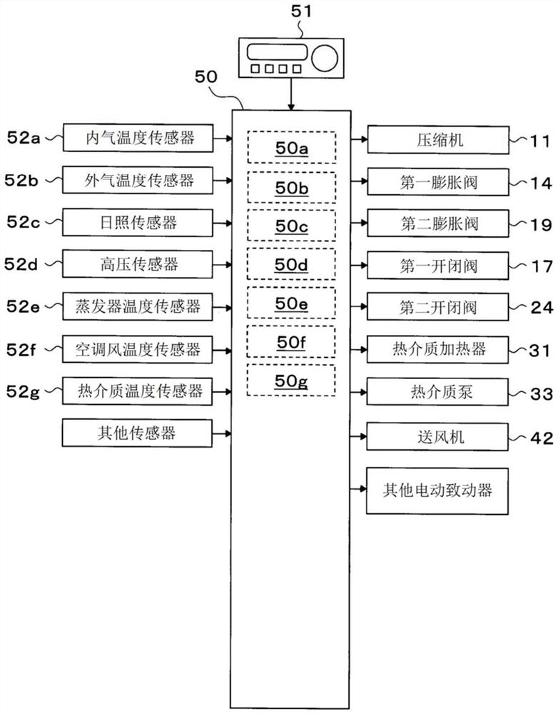
[0279] Next, a second embodiment different from the first embodiment described above will be described with reference to the drawings. A vehicle air conditioner 1 according to the second embodiment is configured to include a refrigeration cycle device 10 , a heat medium circuit 30 , a room air conditioner unit 40 , a control device 50 , and the like, as in the first embodiment.

[0280] In the vehicle air conditioner 1 according to the second embodiment, the cycle structure of the refrigeration cycle device 10 is different from that of the first embodiment. Since the other configurations of the second embodiment are the same as those of the first embodiment, redundant descriptions will be omitted, and points different from the first embodiment will be described in detail. In addition, in the following description, the same code|symbol as 1st Embodiment shows the same structure, and the preceding description is referred.

[0281] Such as Figure 7 As shown, the refrigeration ...


PUM


Abstract

This air conditioner (1) comprises a heat medium circuit (30), a refrigeration cycle device (10), a discharge capacity control unit (50a), a heat generation amount control unit (50b), a target temperature determination unit (50c), and an upper limit determination unit (50d). The heat medium circuit has a heat exchanger (32) for heating and an electric heater (31). The refrigeration cycle device heats the heat medium by exchanging heat between the heat medium of the heat medium circuit and the high-temperature and high-pressure refrigerant discharged from the electric compressor (11). The air conditioner is operated by switching between a heater priority control mode and a compressor priority control mode. In the heater priority control mode, the rotational speed (Nc) of the electric compressor is brought close to the upper limit (NcMAX), and the amount of heat generated by the electric heater is increased with an increase in temperature difference (TWO-TW). In the compressor priority control mode, the amount of heat generated by the electric heater is decreased, and the rotation speed of the electric compressor is increased so as to compensate for the decreased amount of heat generated.

Description

[0001] Cross-references to related applications [0002] This application is based on Japanese Patent Application No. 2018-110426 filed on June 8, 2018, and the contents described therein are incorporated herein by reference. technical field [0003] The invention relates to an air conditioner with a refrigeration cycle and a heat medium circuit. Background technique [0004] Conventionally, there have been various inventions related to vehicle air-conditioning apparatuses for air-conditioning the interior of a vehicle. The invention described in Patent Document 1 is known as an invention related to these vehicle air conditioners. The vehicle air conditioner described in Patent Document 1 includes a vapor compression heat pump cycle (refrigeration cycle) and a heat medium circuit (cooling water circuit). [0005] The vehicle air conditioner disclosed in Patent Document 1 uses a high-temperature and high-pressure refrigerant in a refrigeration cycle and a heat medium heated...

Claims


Application Information

Patent Timeline
IPC IPC(8): B60H1/22
CPCB60H1/00921B60H1/3213B60H2001/3258B60H2001/3272F24F2140/60F24F2140/50F24F11/64F24F2130/10F24F11/46F24F11/67F24F11/89F24F2110/10F24F2110/12F24F2140/20G05B19/042G05B2219/2638
Inventor 加见佑一杉村贤吾大浦光雄
Owner DENSO CORP
Why Eureka
Try Eureka