A Calculation Method for Coupling of Primary and Secondary Loops in Nuclear Power System

A secondary loop, nuclear power technology, applied in the field of nuclear reactor systems, can solve problems such as inability to obtain simulation results and inability to transfer calculation results, and achieve easy coupling realization and modification of calculation models and simulation conditions, guarantee calculation accuracy, and improve The effect of accuracy

Active Publication Date: 2021-12-28
XI AN JIAOTONG UNIV
View PDF5 Cites 0 Cited by
  • Summary
  • Abstract
  • Description
  • Claims
  • Application Information

AI Technical Summary

Problems solved by technology

System analysis programs generally carry out overall one-dimensional modeling of the primary circuit. The steam generator uses a lumped parameter model or a distributed parameter model, and sets the boundary conditions of the part connected to the secondary circuit according to factors such as steam flow and feedwater flow. The calculation results can reflect The flow and heat transfer characteristics of the steam generator under steady state and accident conditions, but for the space with a large free volume inside the steam generator, such as the structure of the inlet chamber, outlet chamber, steam chamber, etc., it cannot be obtained better The simulation results of
Computational fluid dynamics software is limited by calculation conditions and generally only conducts overall three-dimensional modeling of steam generators, using Reynolds-averaged NS model, large eddy simulation, separation vortex and other turbulence solution models, and the boundary conditions use the fitting results of the system analysis program. Passively accept the changes in the working conditions of the primary and secondary circuits, and cannot pass the calculation results back to the system analysis program

Method used


Image

  • A Calculation Method for Coupling of Primary and Secondary Loops in Nuclear Power System
  • A Calculation Method for Coupling of Primary and Secondary Loops in Nuclear Power System

Examples


Embodiment Construction

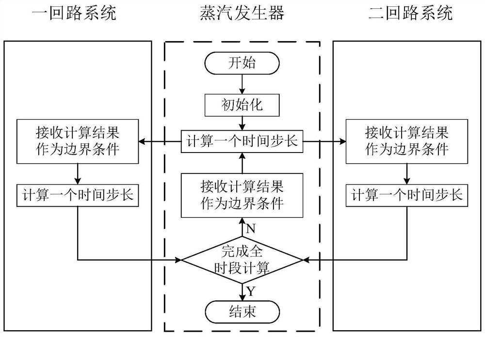
[0020] In the following, the coupling analysis is realized by calling the system analysis program through the user-defined function of the computational fluid dynamics software as an example, and the explicit coupling method and the area division method of overlapping areas are selected, combined with figure 1 Schematic diagram of the coupling process with figure 2 The modeling diagram for further description:

[0021] The invention provides a coupling calculation method for the first and second loops of a nuclear power system, figure 1 A schematic diagram of the coupling process is given. In the figure, the solid line box is the computational domain of the system program, and the dotted line box is the computational fluid dynamics software computational domain. The specific coupling method is as follows:

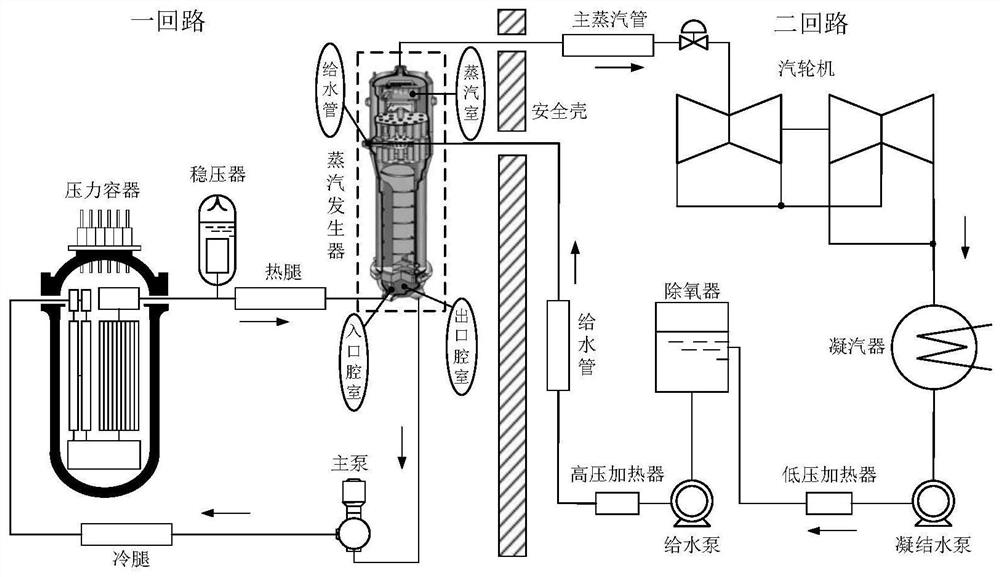
[0022] Step 1: Use the geometric model building software to conduct three-dimensional modeling of the internal components of the steam generator, ignoring the small struc...


PUM


Abstract

The invention discloses a coupling calculation method of one and two circuits of a nuclear power system. The steps are as follows: 1. Establish a three-dimensional geometric model of a reactor steam generator and divide the grid, and establish a one-dimensional simplified model of a nuclear reactor one and two circuits; 2. Use a calculation fluid The dynamics software sets the initial boundary conditions of the geometric model of the steam generator and the initial state of the calculation domain; 3. The computational fluid dynamics software calculates the steam generator model, obtains the calculation results, and transfers the calculation results to the system analysis program as a system analysis The boundary conditions of this time step of the program; 4. The system analysis program calculates the first and second loop models, obtains the calculation results, and transmits the calculation results to the computational fluid dynamics software as the calculation time of the next time step of the computational fluid dynamics software 5. Repeat steps 3 and 4 until the reactor system model completes the full-time calculation. Complete the multi-dimensional and high-fidelity coupling analysis of the reactor system.

Description

technical field [0001] The invention belongs to the technical field of nuclear reactor systems, and in particular relates to a coupling calculation method for primary and secondary loops of a nuclear power system. Background technique [0002] The steam generator is an important device connecting the primary and secondary loops in the nuclear reactor system. It has an important function of transferring heat from the primary loop to the secondary loop under normal operation and certain accident conditions. It is the focus of the coupling calculation of the primary and secondary loops. There are two kinds of analysis methods for steam generators: system analysis program and computational fluid dynamics program. System analysis programs generally carry out overall one-dimensional modeling of the primary circuit. The steam generator uses a lumped parameter model or a distributed parameter model, and sets the boundary conditions of the part connected to the secondary circuit acco...

Claims


Application Information

Patent Timeline
Patent Type & Authority Patents(China)
IPC IPC(8): G06F30/28G06F30/10G06F30/23G06F113/08G06F119/14
CPCG06F30/28G06F30/10G06F30/23G06F2113/08G06F2119/14
Inventor 王明军霍雨辰余浩田文喜秋穗正苏光辉
Owner XI AN JIAOTONG UNIV
Why Eureka
Try Eureka