Constant-temperature air circulation system

An air circulation system, constant temperature technology, applied in air conditioning systems, heating and ventilation control systems, heating and ventilation safety systems, etc.

Active Publication Date: 2021-01-15
武汉微环控技术有限公司
View PDF18 Cites 2 Cited by
  • Summary
  • Abstract
  • Description
  • Claims
  • Application Information

AI Technical Summary

Problems solved by technology

[0005] Aiming at the defects of the prior art, the purpose of the present invention is to provide a constant temperature air circulation system, aiming to solve the problems that the existing air constant temperature device cannot be cooled, the adjustment range is small, or it can be cooled and heated but cannot save energy

Method used


Image

  • Constant-temperature air circulation system
  • Constant-temperature air circulation system
  • Constant-temperature air circulation system

Examples


Embodiment Construction

[0038] In order to make the object, technical solution and advantages of the present invention clearer, the present invention will be further described in detail below in conjunction with the accompanying drawings and embodiments. It should be understood that the specific embodiments described here are only used to explain the present invention, not to limit the present invention.

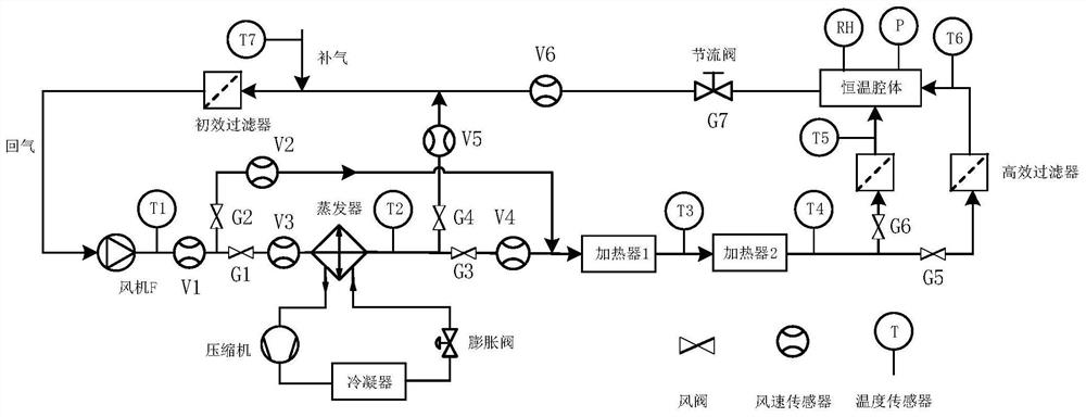
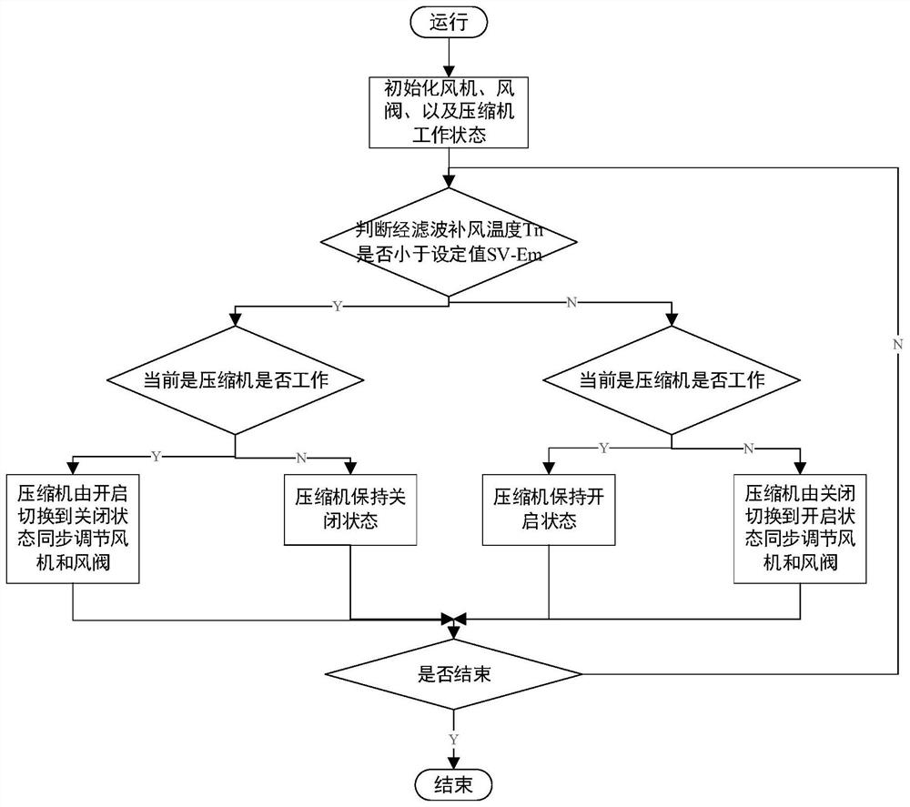
[0039] The constant-temperature circulating air system in the present invention proposes a long-term operation, stable and energy-saving solution based on multi-level temperature control, and can switch the state of the compressor adaptively according to the fresh air temperature. Two important circuits are designed to bypass the gas flowing through the compressor and the cavity. By adjusting the opening of the fan and the air valve, the flow adjustment when the compressor is switched is avoided to prevent it from interfering with the cavity temperature.

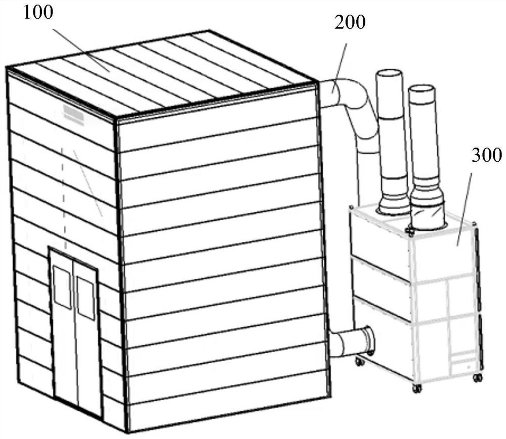
[0040] Such as figure 1 As shown, the con...


PUM


Abstract

The invention provides a constant-temperature air circulation system. Air valves are assembled behind two three-way joints of parallel bypasses and a main circulation loop for adjusting the air flow of each branch, and when the current state of a compressor is kept unchanged, a fan and the air valves are not changed. When the compressor in the turn-on state needs to be turned off , the air volumeof the fan is adjusted, and the flow of the bypasses and the main path is synchronously adjusted until all air valves controlling the flow of an evaporator are closed and all the air valves of the bypasses are opened. When the compressor in the turn-off state needs to be turned on, the air volume of the fan is adjusted, and the flow of the bypasses and the main path is synchronously adjusted untilall the air valves controlling the flow of the evaporator are opened and all the air valves of the bypasses are closed. Air valve adjustment is matched with compressor state switching to always guaranteed that the flow from a heater to a cavity is unchanged. The working state of a refrigeration heat exchange device is switched through bypass assistance to save energy for the system, and the flowand temperature of gas flowing through the constant-temperature cavity are not affected while it is guaranteed that the working state of the refrigeration heat exchange device is switched.

Description

technical field [0001] The invention belongs to the field of constant temperature air circulation system, and more specifically relates to a constant temperature air circulation system. Background technique [0002] The micro-environment purification device is mostly used to provide a constant temperature, constant humidity and clean environment for semiconductor manufacturing equipment and precision measurement equipment. Most of the micro-environment devices and purification rooms in the prior art use air-conditioning units composed of compressors, evaporators, condensers, and expansion valves for temperature control or improved technologies include temperature control systems based on air-conditioning units connected in series with heaters. . However, the existing technology does not take into account that turning off the compressor under certain working conditions can also ensure temperature stability and save energy while ensuring temperature stability, and the impact ...

Claims


Application Information

Patent Timeline
Patent Type & Authority Applications(China)
IPC IPC(8): F25B29/00F25B41/20F25B49/02
CPCF25B29/003F25B49/02F24F1/022F24F11/74F24F2110/10F24F13/08F24F11/81F24F2110/30Y02B30/70F24F11/77F24F1/028F24F1/0323F24F13/30F24F2221/54
Inventor 李小平曹迪王剑晖王锦春
Owner 武汉微环控技术有限公司
Why Eureka
Try Eureka