Integrated environment control device and environment control method

A control device, an integrated technology, applied in the substation/distribution device shell, substation/switchgear cooling/ventilation, heating methods, etc., can solve the problems of reducing electrical distance, humidity hazards of electrical equipment, and reducing insulation, etc. Achieve the effect of ensuring air safety, improving cooling effect and reducing working power

Active Publication Date: 2021-05-14
ZHEJIANG DUMEI ELECTRIC POWER TECH
View PDF7 Cites 1 Cited by
  • Summary
  • Abstract
  • Description
  • Claims
  • Application Information

AI Technical Summary

Problems solved by technology

[0007] (1) The dew formed on the secondary terminal block in the terminal box mechanism box will corrode the metal conductive parts on the terminal block. If the corrosion is heavy or mixed with other impurities such as dust, it will easily cause AC and DC short circuit grounding, and DC grounding will affect the substation. The stable operation of the secondary system has caused great harm. Actual operating experience shows that the DC grounding is mostly caused by water adhering to the live parts, and what is more serious is that the dew even causes a short circuit between the two secondary lines on the terminal block. If it happens to be the switch trip circuit, it will immediately cause the switch to malfunction and cause a power outage.
[0008] (2) The dew formed on the switch or knife switch operating mechanism will corrode the metal parts in the mechanism, affect the service life of the mechanism, and even cause the mechanism to jam due to corrosion, resulting in the mechanism not operating in place when the switch or knife switch is opened and closed , if the moving and static contacts of the switch are opened and closed slowly, it will cause a huge electrical accident, especially when the switch has not been operated for a long time, the corrosion phenomenon will be more serious
[0009] (3) The high-voltage room generally pays more attention to ventilation, so the indoor temperature and humidity are greatly affected by the outdoor environment. Condensation is also prone to occur in the indoor high-voltage switch cabinet, and the insulating porcelain bottles in the cabinet are mostly not considered waterproof. If there is dew on it, it will Reduce its insulation, and may even cause creepage or flashover, which seriously affects the normal operation of the equipment, especially when some equipment is out of service, its internal temperature is lower, and it is easier to form condensation on its surface. prone to accidents
[0010] 2. High indoor temperature and humidity;
[0011] Electrical equipment is vulnerable to humidity during use. If it is used for a long time in a high humidity environment, the electronic components of the control equipment will cause failure.
[0012] 3. A large area of ​​indoor dust accumulation is serious;
[0013] The generation of dust not only pollutes the environment, damages people's health, but also brings great harm to the safe operation of electrical equipment.
[0014] (1) Dust condenses and settles around the electrical equipment, thereby reducing the electrical distance, destroying the insulation strength of the electrical equipment, and easily causing electrical breakdown and short circuit accidents during line overvoltage or electrical operation
[0015] (2) Poor contact of the electrical switch is caused. Dust accumulation between the contacts of the electrical switch and between the electromagnet cores will cause poor contact of the electrical switch, especially in the control circuit of the relay contactor.
The action of the electrical control system is unstable, sometimes good and sometimes bad, and the phenomenon of single-phase operation contact adhesion and other phenomena often cause equipment accidents
[0016] 4. Indoor toxic gas accumulation;
[0017] Affect the physical and mental health of operation and maintenance personnel
[0018] Some of the above situations will bring certain safety hazards to the normal operation of the equipment.

Method used


Image

  • Integrated environment control device and environment control method
  • Integrated environment control device and environment control method
  • Integrated environment control device and environment control method

Examples


Embodiment Construction

[0061] The following will clearly and completely describe the technical solutions in the embodiments of the present invention with reference to the drawings in the embodiments of the present invention.

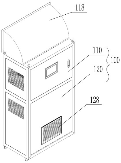
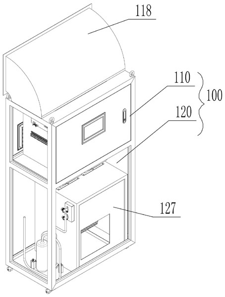
[0062] The integrated environmental control device includes an integrated body 100 installed in the power distribution room; the body 100 separates a heat dissipation cavity 110 and an indoor cavity 120 . Preferably, the heat dissipation cavity 110 is located above the indoor cavity 120 . Of course, it is also possible for the heat dissipation cavity 110 to be located on the side of the indoor cavity 120 .

[0063] The heat dissipation cavity 110 is provided with a heat dissipation passage.

[0064] The heat dissipation chamber 110 is provided with a heat dissipation fresh air outlet 111 and a heat dissipation air outlet 117, and the heat dissipation chamber 110 is equipped with a heat dissipation fan 114 and a condenser 115; the air outlet of the condenser 115 is connected w...


PUM


Abstract

An integrated environment control device and an environment control method, belonging to the technical field of power transformation and ventilation equipment, including an integrated body installed in a power distribution room; the body separates a heat dissipation cavity and an indoor cavity; the heat dissipation cavity A heat dissipation passage is provided; the indoor cavity is provided with a fresh air passage and an indoor return air passage. When the temperature outside the power distribution room is lower than the temperature inside the power distribution room, the temperature of the power distribution room is reduced by introducing fresh air with a low external temperature without turning on the evaporator. This scheme of reducing the indoor temperature by replacing the air greatly reduces the working power required by the equipment, and has the advantages of energy saving and high efficiency. At the same time, since the replaced air contains toxic gas and dust, the introduction of fresh air ensures the air safety of the working environment inside the power distribution room.

Description

technical field [0001] The invention belongs to the technical field of power-changing ventilation equipment, and in particular relates to an integrated environment control device and an environment control method. Background technique [0002] With the development and popularization of computers, the number of computer systems is increasing day by day, and the supporting environmental equipment is also increasing. Intelligent power distribution rooms have become a trend. The equipment in the power distribution room must provide users with a normal power consumption environment at all times. Once the equipment fails, it will affect the electricity consumption of users, and pose a threat to the normal work and life of enterprises, institutions, and families. If the accident is serious and cannot be handled in time, it may damage the hardware equipment and cause serious consequences. [0003] At present, the power distribution network is getting bigger and bigger, and the mana...

Claims


Application Information

Patent Timeline
Patent Type & Authority Patents(China)
IPC IPC(8): F24F1/028F24F1/022F24F1/0323F24F1/035F24F1/0358F24F13/08F24F13/28F24F13/30H02B1/28H02B1/56
CPCF24F1/028F24F1/022F24F1/0323F24F1/035F24F1/0358F24F13/08F24F13/28F24F13/30H02B1/565H02B1/28
Inventor 张晓勇徐元明胡敏卢俊毅
Owner ZHEJIANG DUMEI ELECTRIC POWER TECH
Why Eureka
Try Eureka