A Second Tool Setting Method for 3+2 Axis Machine Tool Machining

A technology of secondary tool setting and machine tool, applied in metal processing, metal processing equipment, metal processing mechanical parts, etc., can solve the problems of no re-confirmation and difficult tool setting for secondary tool setting, etc.

Active Publication Date: 2021-08-17
广州傲创智能科技有限公司
View PDF4 Cites 0 Cited by
  • Summary
  • Abstract
  • Description
  • Claims
  • Application Information

AI Technical Summary

Problems solved by technology

[0003] However, every time the cutter head of the machine tool swings the position, the cutting point of the cutter on the cutter head will have a certain error due to the rotation of the two rotating axes. Usually, this error is not reconfirmed or only a certain local position on the workpiece is trial-processed. The error It is necessary to re-diagonal the tool on the cutter head to reduce the problem that the tool on the cutter head has a large deviation between the actual size of the workpiece and the size of the drawing due to the error deviation of the cutter head position
However, since the workpiece has already been installed on the working platform of the existing machine tool, and the surface of the workpiece has been beveled in the first step in the early stage, it is difficult to realize the second tool setting of the tool on the tool head during the machining process of the workpiece.

Method used


Image

  • A Second Tool Setting Method for 3+2 Axis Machine Tool Machining
  • A Second Tool Setting Method for 3+2 Axis Machine Tool Machining
  • A Second Tool Setting Method for 3+2 Axis Machine Tool Machining

Examples


Embodiment 2

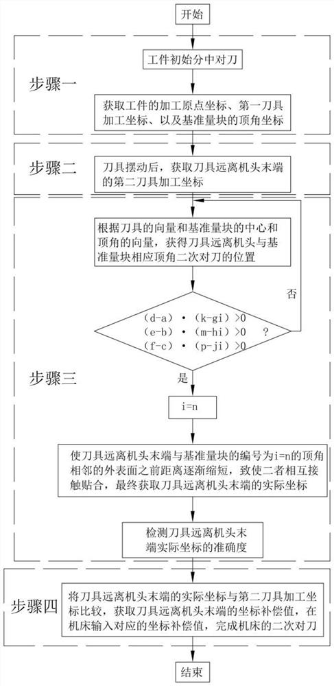
[0072] The difference between embodiment two and embodiment one is:

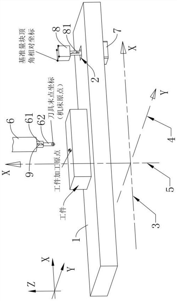
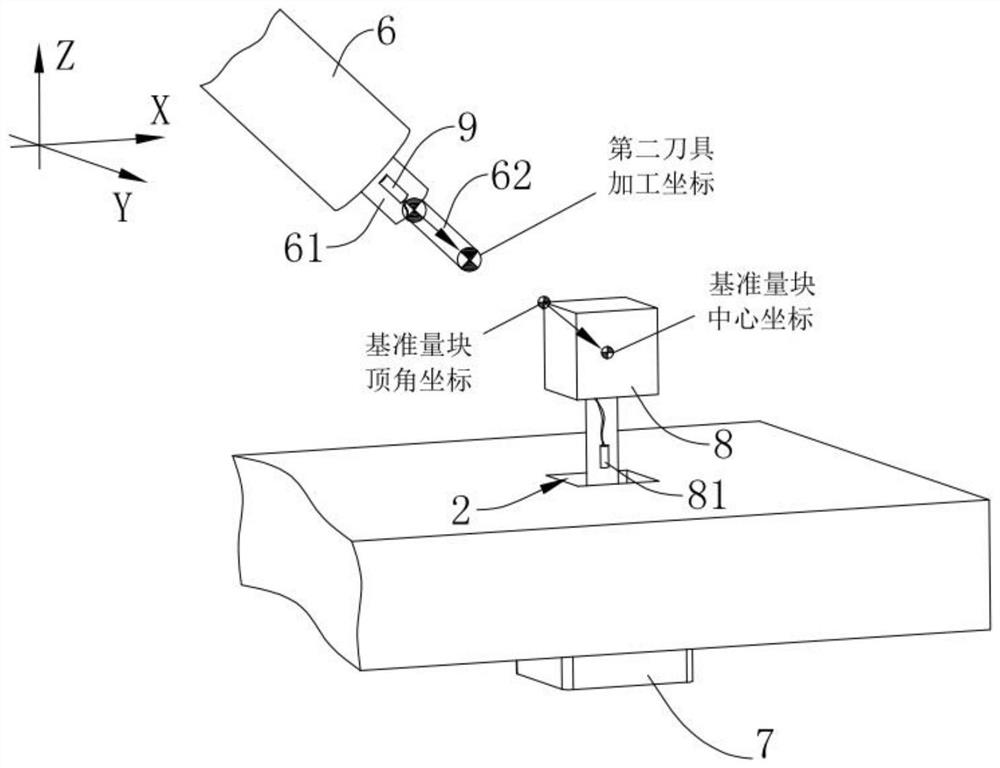
[0073] The 3+2-axis machine tool includes a support frame (not shown in the figure), the support frame is fixedly connected to the working platform 1, and the working platform 1 is embedded with a pusher, the pusher is the push cylinder 7, and the push cylinder 7 is completely accommodated and In the working platform 1, the protruding end of the pushing cylinder 7 is set perpendicular to the supporting surface of the working platform 1 toward the machine head 6, and the protruding end of the pushing cylinder 7 is fixedly connected with a reference gauge block 8, which is set in a cube. The three adjacent edges of any top angle of the gauge block 8 are respectively parallel to the length direction of the X-axis driving part 3, the Y-axis driving part 4 and the Z-axis driving part 5 of the machine tool. The supporting surface of the working platform 1 There is a storage slot 2 for inserting the reference gauge...


PUM


Abstract

The invention discloses a secondary tool setting method for 3+2 axis machine tool processing, which comprises the following steps: Step 1: initial tool setting of the workpiece, obtaining the initial coordinates of the machining origin of the workpiece and the apex coordinates of the reference gauge block; Step 2 : After oscillating the tool, obtain the second tool machining coordinates of the tool tip; Step 3: Move the movable parts of the machine tool so that the tool tip is in contact with the three outer surfaces adjacent to one top corner of the reference gauge block, and obtain the tool tip’s coordinates Actual coordinates; Step 4: Compare the actual coordinates of the tool nose with the machining coordinates of the second tool in Step 2 to obtain the tool nose coordinate compensation value, and input the coordinate compensation value of the second tool machining coordinates in the machine tool to complete the secondary alignment of the machine tool Knife. By adopting the above steps, it has the function of performing secondary tool setting after the tool on the tool head rotates and swings around the A-axis or the C-axis, and reduces the error of the tool on the tool head.

Description

technical field [0001] The invention relates to the technical field of machine tool setting, in particular to a secondary tool setting method for 3+2 axis machine tool processing. Background technique [0002] The 3+2-axis machine tool is a kind of five-axis machine tool. The five-axis machine tool is also called the five-axis linkage CNC machine tool. It has the characteristics of high efficiency and high precision. The 3 axes of the 3+2 axis machine tool are divided into X, Y, and Z axes according to the spatial coordinates, and the other 2 axes are the rotating shaft rotating around the X axis and the rotating shaft rotating around the Z axis, called A axis and C (B) axis, 3+2 axis machine tool when processing the mold, the molding surface of the mold core in the mold will usually form a corresponding concave or convex shape due to the shape of the product. During the processing, the tool on the machine tool head will The tool is set for the first time, and then the work...

Claims


Application Information

Patent Timeline
Patent Type & Authority Patents(China)
IPC IPC(8): B23Q15/22B23Q3/00
CPCB23Q3/00B23Q15/22
Inventor 杨书荣梁恒杨宋周炜明胡学有
Owner 广州傲创智能科技有限公司
Why Eureka
Try Eureka