
Machining center magnetic scrap iron removing device and scrap iron removing method

A machining center and iron filing technology, applied in metal processing equipment, metal processing machinery parts, manufacturing tools, etc., can solve the problems of inability to provide effective guarantee for machining center operation requirements, reduce filtration efficiency, and fail to achieve continuous operation.

Active Publication Date: 2021-01-12
广东铨冠智能科技有限公司
View PDF15 Cites 0 Cited by
  • Summary
  • Abstract
  • Description
  • Claims
  • Application Information

AI Technical Summary

Problems solved by technology

In response to this problem, some equipment that utilizes electromagnetic adsorption to remove iron filings has emerged as the times require. For example, Chinese patents CN 209918070 U, CN110000604 A and CN 211246950 U all disclose chip removal devices using electromagnetic adsorption for iron filings. Unable to achieve continuous operation, it is still necessary to stop the operation after filtering for a period of time to clean the internal filter device, which reduces the filtration efficiency and cannot provide effective guarantee for the operation requirements of the machining center

Method used


Image

  • Machining center magnetic scrap iron removing device and scrap iron removing method
  • Machining center magnetic scrap iron removing device and scrap iron removing method
  • Machining center magnetic scrap iron removing device and scrap iron removing method

Examples


Embodiment Construction

[0029] The present invention will be further described below in conjunction with the accompanying drawings and embodiments.

[0030] The structures, proportions, sizes, etc. shown in the drawings attached to this specification are only used to match the content disclosed in the specification for the understanding and reading of those who are familiar with this technology, and are not used to limit the conditions for the implementation of the present invention , so it has no technical substantive meaning, and any modification of structure, change of proportional relationship or adjustment of size shall still fall within the scope of the disclosure of the present invention without affecting the functions and objectives of the present invention. within the scope of the technical content covered. At the same time, terms such as "upper", "lower", "left", "right", "middle" and "one" quoted in this specification are only for the convenience of description and are not used to limit th...


PUM


Abstract

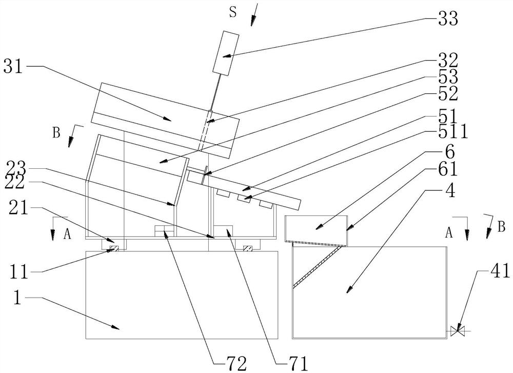
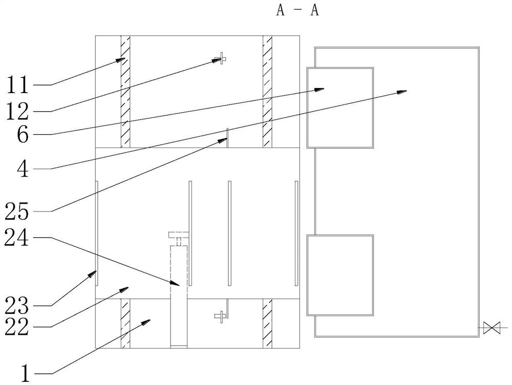
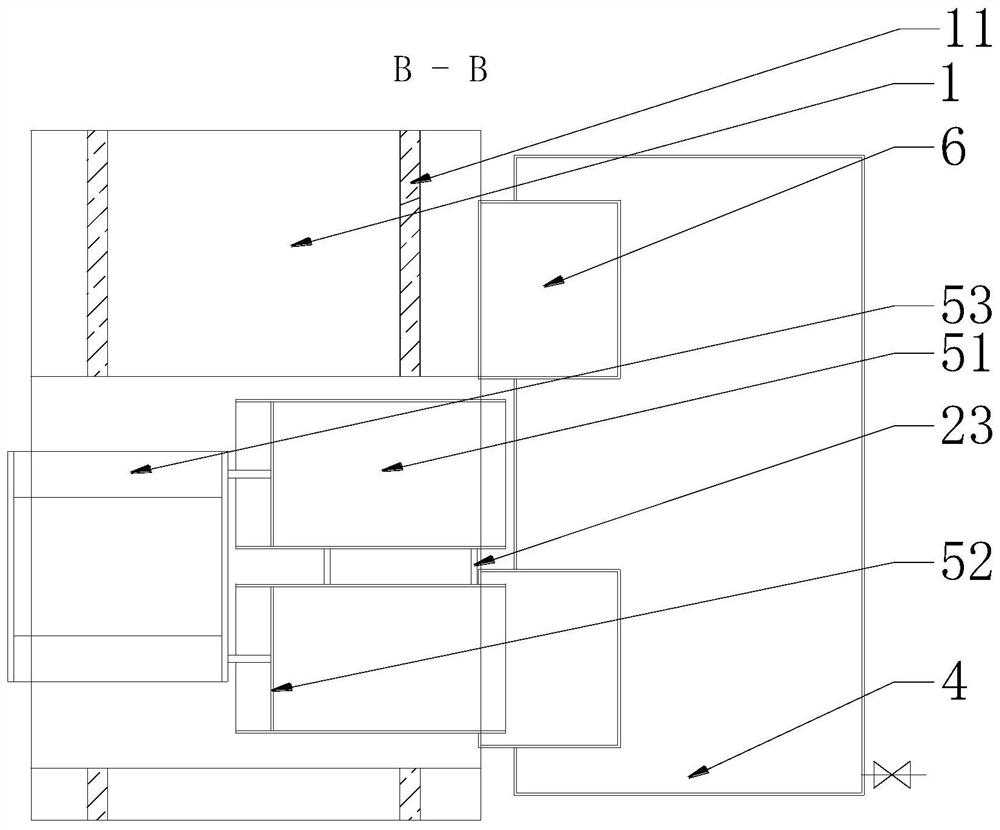
The invention discloses a machining center magnetic scrap iron removing device. The machining center magnetic scrap iron removing device comprises a machine frame, a sliding support, a flow guide module, a water storage tank, adsorption modules and two scrap iron boxes which are standby for each other, the machine frame is a hollow cuboid, two parallel guide rails are welded to the upper side faceof the machine frame, inverted-U-shaped steel bars are welded to the left side and the right side of the machine frame, a transverse section of each steel bar is welded to the flow guide module, theflow guide module is fixed to the upper portion of the rack, the sliding support is placed on the guide rails through four sliding blocks welded and fixed to the lower side face, the adsorption modules are welded and fixed to the sliding support, and the two scrap iron boxes are welded to the water storage tank. According to the machining center magnetic scrap iron removing device, by arranging the two adsorption units and scrap iron boxes which are standby for each other, automatic continuous operation of the whole device is achieved through PLC control, filtered scrap iron can be cleaned without shutdown, effective guarantee is provided for continuous operation of a machining center, and the device is simple in structure and reasonable in design and has extremely high economic benefits and use significance.

Description

technical field [0001] The invention relates to a coolant recycling and filtering device, in particular to a magnetic chip removal device and method for a machining center. Background technique [0002] When the machining center is processing iron parts, a large amount of iron filings will be left. These iron filings will remain in the machining coolant. These iron filings will be discharged into the coolant tank along with the cooling liquid. When the chip coolant is repeatedly extracted and used, it is not only easy to damage the blades of the water pump, but also the coolant containing iron chips will cause damage to the cutting tools used in processing and the processed parts, which will increase the operation and maintenance costs. . Most of the markets on the market use multiple filtration methods to remove iron filings in the coolant, but there are still fine iron filings remaining in the coolant. In response to this problem, some equipment that utilizes electromagn...

Claims


Application Information

Patent Timeline
IPC IPC(8): B23Q11/00
CPCB23Q11/0064Y02P70/10
Inventor 刘淑英
Owner 广东铨冠智能科技有限公司
Learn More