
Fluid trace injection device

A spraying device and fluid technology, applied in the direction of spraying devices, spraying devices, etc., can solve problems affecting the quality of fluid spraying, wear, and gaps, and achieve the effects of ensuring the quality of fluid spraying, improving the quality of fluid spraying, and facilitating installation and disassembly

Pending Publication Date: 2021-01-12
CHANGZHOU MINGSEAL ROBOT TECH CO LTD
View PDF0 Cites 4 Cited by
  • Summary
  • Abstract
  • Description
  • Claims
  • Application Information

AI Technical Summary

Problems solved by technology

Since the end of the lever slides horizontally with the upper plane of the closing element during the swing process, the closing element will be subjected to a reciprocating lateral force during the up and down movement, which will cause mutual friction between the closing element and the guide element, affecting Fluid Jet Quality
[0004] In addition, the existing fluid micro-injection device realizes the transmission of displacement and force value through the tangent between the large circular arc concave surface of the lever and the small cylindrical surface of the lever shaft. However, due to the uncertainty of the tangent position between the large circular arc and the small cylinder, the lever amplification ratio is different. Thus affecting the consistency of multiple sets of fluid micro-injection devices
[0005] On the other hand, by using the guide seat of the closing element (hitter) to cooperate with the shaft hole of the fluid seat, the axis of the closing element is coaxial with the axis of the fluid chamber of the fluid seat, and at the same time, the size of the actuator system and the flow channel assembly are matched to limit the closing The displacement of the element (firing pin) guide seat along the axis; however, wear will occur during long-term operation, resulting in a gap between the closing element (firing pin) guiding seat and the fluid seat, causing the closing element and the axis of the fluid chamber to be out of axis. The injection quality of the fluid micro-injection device affects the

Method used


Image

  • Fluid trace injection device
  • Fluid trace injection device
  • Fluid trace injection device

Examples


Embodiment Construction

[0064] Embodiments of the present invention are described in detail below, examples of which are shown in the drawings, wherein the same or similar reference numerals designate the same or similar elements or elements having the same or similar functions throughout. The embodiments described below by referring to the figures are exemplary only for explaining the present invention and should not be construed as limiting the present invention.

[0065] In describing the present invention, it should be understood that the terms "center", "longitudinal", "transverse", "length", "width", "thickness", "upper", "lower", "front", " Back", "Left", "Right", "Vertical", "Horizontal", "Top", "Bottom", "Inner", "Outer", "Clockwise", "Counterclockwise", "Axial", The orientation or positional relationship indicated by "radial", "circumferential", etc. is based on the orientation or positional relationship shown in the drawings, and is only for the convenience of describing the present invent...


PUM


Abstract

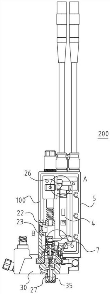
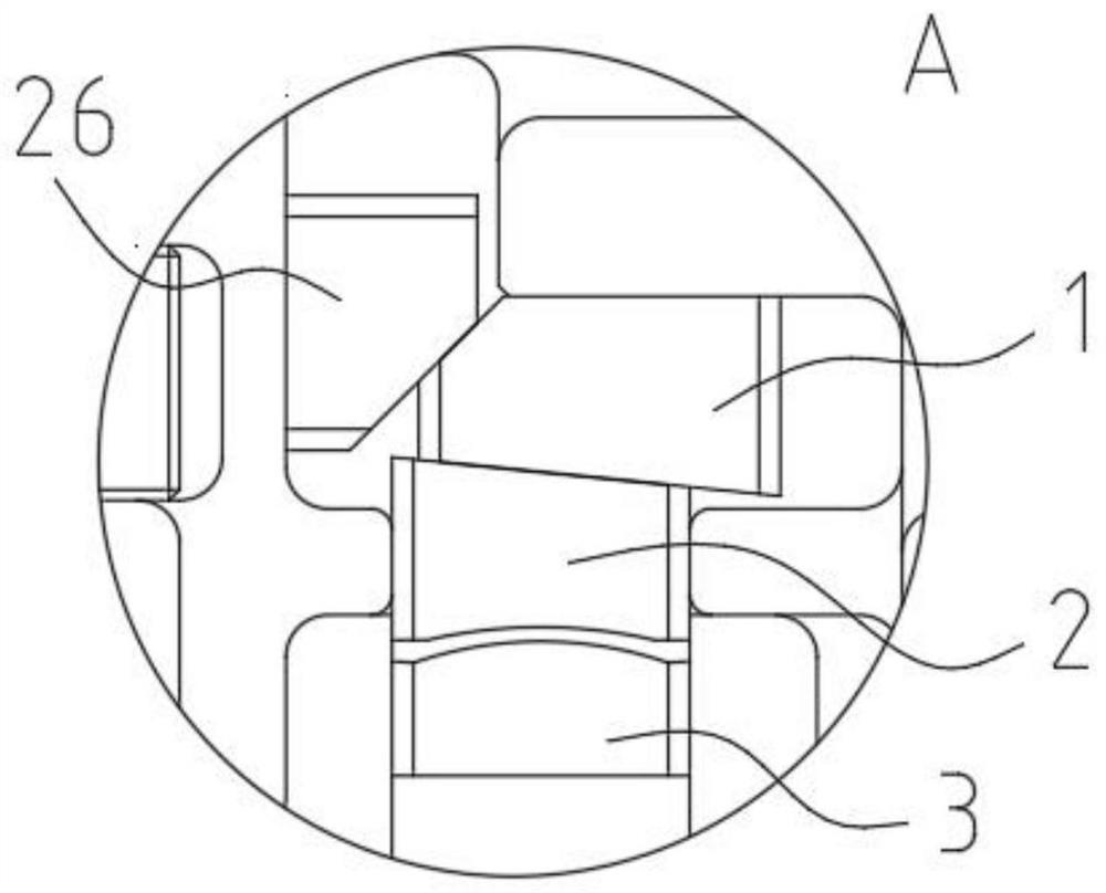
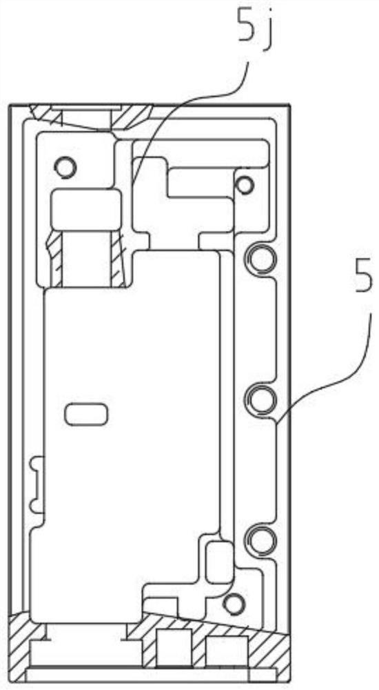
The embodiment of the invention discloses a fluid trace injection device. The fluid trace injection device comprises a base body, a lever, an actuator, a fluid seat, a nozzle, a guide seat and a movable element, wherein an execution mechanism mounting cavity is defined in the base body, and a positioning hole is formed in the base body; the lever is arranged in the execution mechanism mounting cavity, and the two ends of the lever are movable; the actuator is telescopically arranged in the execution mechanism mounting cavity and connected with one end of the lever; the base body is arranged onthe fluid seat; the nozzle is arranged on the fluid seat; a guide hole penetrating in the axial direction of the guide seat is defined in the guide seat, the lower end of the guide seat extends intothe mounting cavity and is in threaded connection with the fluid seat, and the upper end of the guide seat can extend into the positioning hole when the base body and the fluid seat are assembled; andthe movable element is arranged in the guide hole and can move in the axial direction of the guide seat, and the upper end of the movable element is connected with the other end of the lever in a clamped mode when the base body and the fluid seat are assembled and driven by the lever to move in the axial direction of the positioning hole. According to the fluid trace injection device, the servicelife is long, and the fluid injection quality stability is high.

Description

technical field [0001] The invention belongs to the technical field of piezoelectric valves, and in particular relates to a fluid micro-injection device. Background technique [0002] On the one hand, existing fluid micro-injection devices usually use a wedge-shaped pre-tensioning mechanism to adjust the pre-pressure of the piezoelectric actuator. The injection quality of the device is affected, resulting in unstable fluid injection quality. [0003] On the other hand, the swing of the lever mechanism directly drives the closing element to move up and down along the axis of the fluid cavity, so as to realize the opening and closing between the closing element and the nozzle, thereby realizing fluid injection. Since the end of the lever slides horizontally with the upper plane of the closing element during the swing process, the closing element will be subjected to a reciprocating lateral force during the up and down movement, which will cause mutual friction between the clo...

Claims


Application Information

Patent Timeline
IPC IPC(8): B05B1/30B05B12/08
CPCB05B1/30B05B12/087
Inventor 曲东升闵继江孙培李长峰冒洋洋耿玉新上官鑫龙
Owner CHANGZHOU MINGSEAL ROBOT TECH CO LTD
Learn More