Eureka AIR delivers breakthrough ideas for toughest innovation challenges, trusted by R&D personnel around the world.

A dual-frequency antenna and antenna array

A dual-frequency antenna and antenna technology, which is applied in the direction of antenna array, antenna, antenna grounding switch structure connection, etc., can solve the problems of unfavorable cost control, high insertion loss of MEMS switches, etc., and achieve size reduction, good directivity, and integration Effect

Active Publication Date: 2021-10-08
HUAZHONG UNIV OF SCI & TECH
View PDF19 Cites 0 Cited by
  • Summary
  • Abstract
  • Description
  • Claims
  • Application Information

AI Technical Summary

Problems solved by technology

[0007] However, there are still many deficiencies in the existing optically controlled microwave switches. For example, compared with MEMS switches, they have higher insertion loss. The excitation light source needs to use lasers, which is not conducive to cost control. Therefore, it is necessary to study how to improve the optically controlled microwave switches. electrical properties

Method used


Image

  • A dual-frequency antenna and antenna array
  • A dual-frequency antenna and antenna array
  • A dual-frequency antenna and antenna array

Examples


Embodiment Construction

[0044] In order to make the object, technical solution and advantages of the present invention clearer, the present invention will be further described in detail below in conjunction with the accompanying drawings and embodiments. It should be understood that the specific embodiments described here are only used to explain the present invention, not to limit the present invention.

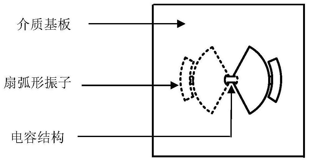
[0045] Such as figure 1 As shown, it is a schematic diagram of the overall structure of a dual-frequency antenna provided by the present invention, including: a dielectric substrate and a fan-shaped vibrator;

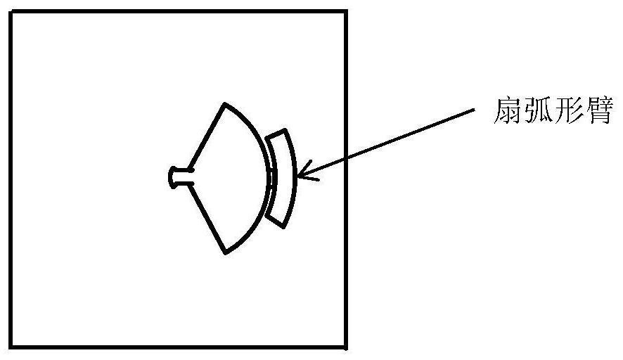
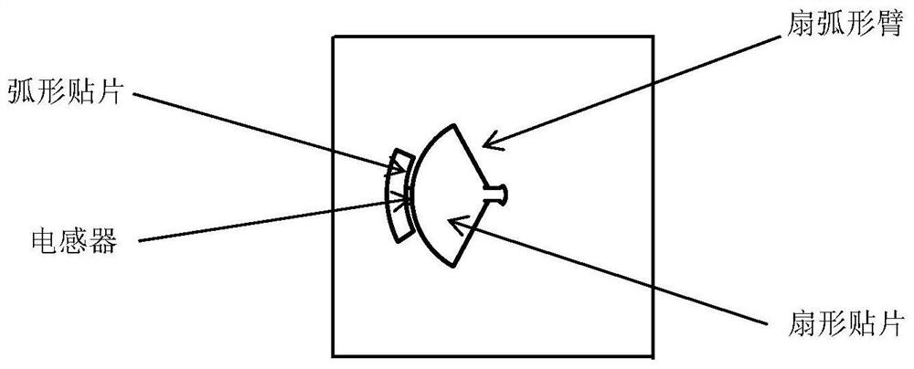
[0046] The fan-shaped vibrator includes two fan-shaped arms, and the two fan-shaped arms are respectively located on the front and back of the dielectric substrate;

[0047] Each fan-shaped arm includes a fan-shaped patch and an arc-shaped patch, the fan-shaped patch is connected to the arc-shaped patch through an inductor, and the other end of the fan-shaped patch is connected to a capacit...


PUM


Abstract

The invention discloses a dual-frequency antenna and an antenna array. The dual-frequency antenna includes: a dielectric substrate and a fan-shaped vibrator; the fan-shaped vibrator includes two fan-shaped arms, wherein each fan-shaped arm consists of a The fan-shaped patch and an arc-shaped patch are composed, the fan-shaped patch and the arc-shaped patch are connected through an inductor, and the other end of the fan-shaped patch is connected to the capacitor structure; the capacitor structure is located in the middle of the fan-shaped vibrator, and consists of two It consists of parallel patches, and the two parallel patches are respectively located at opposite positions on the front and back of the dielectric substrate; the fan-shaped patch and the arc-shaped patch are connected through an inductor, so as to realize dual-frequency operation. In this way, the present invention can realize dual-frequency operation with only one vibrator, effectively reducing the overall size of the dual-frequency antenna. In addition, the dual-frequency antenna provided by the present invention may further include a parasitic unit, and a switch is loaded in the middle of the parasitic unit, and the effect of the parasitic unit is changed by controlling the switch to be turned on and off, so as to realize pattern reconstruction.

Description

technical field [0001] The invention belongs to the technical field of wireless communication, and more specifically relates to a dual-frequency antenna and an antenna array. Background technique [0002] Due to the wide use of wireless LAN, the 2.4GHz frequency band is overloaded, so it needs to be expanded to 2.4GHz and 5GHz dual frequency bands. However, the existing dual-frequency antenna often needs to be realized by two vibrators, and the volume is relatively large, which is not conducive to the integration of the entire antenna. [0003] With the development of wireless communication systems, pattern reconfigurable antennas have been widely studied. Pattern reconfigurable antennas can reduce interference, improve security, and reduce energy loss by directional transmitting signals. Dual-band pattern reconfigurable antennas are the technology for this need. [0004] The reconfigurable antenna can change the current distribution of the antenna to make it have multipl...

Claims


Application Information

Patent Timeline
Patent Type & Authority Patents(China)
IPC IPC(8): H01Q1/36H01Q1/38H01Q1/50H01Q5/20H01Q21/00
CPCH01Q1/36H01Q1/38H01Q1/50H01Q21/00H01Q5/20
Inventor 李青侠熊冰詹再果张玉珍
Owner HUAZHONG UNIV OF SCI & TECH
Why Eureka
Eureka Blog
Learn More