
Tin plating tool

A technology of tinning and tooling, applied in the direction of workpiece clamping devices, auxiliary devices, manufacturing tools, etc., can solve the problems of inability to clamp workpieces, inconvenient use, and single pressing method, so as to improve fastening and applicability , The effect of improving work efficiency

Pending Publication Date: 2021-01-08
刘欣鑫
View PDF7 Cites 0 Cited by
  • Summary
  • Abstract
  • Description
  • Claims
  • Application Information

AI Technical Summary

Problems solved by technology

[0003] When tin-plated parts are processed and produced, such as drilling or welding, they need to be pressed and fixed. The existing pressing usually uses the rotation of the threaded rod to drive the movement of the pressing block to clamp the workpiece. However, this kind of pressing The tightening method requires continuous rotation of the screw to realize the clamping of the workpiece by the clamping block. The efficiency of the clamping process is low and it is inconvenient to use; moreover, the existing clamping block compresses the workpiece through multiple clamping blocks, and the clamping method is single , so that it is impossible to clamp the workpiece better. At the same time, the pressing force of each pressing block on the workpiece is different, which easily causes the problem of uneven force on the surface of the workpiece.

Method used


Image

  • Tin plating tool
  • Tin plating tool
  • Tin plating tool

Examples


Embodiment Construction

[0034]The technical solutions in the embodiments of the present invention will be clearly and completely described below in conjunction with the accompanying drawings in the embodiments of the present invention. Obviously, the described embodiments are only a part of the embodiments of the present invention, rather than all the embodiments. Based on the embodiments of the present invention, all other embodiments obtained by those of ordinary skill in the art without creative work shall fall within the protection scope of the present invention.

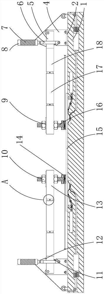
[0035]SeeFigure 1 to Figure 10, The present invention provides a technical solution: a tinning tooling, comprising a workbench 1, on which a tinned part 15 is placed on the upper surface of the workbench 1, and the upper surface of the workbench 1 is fixedly connected with two symmetrical distributions The pressing mechanism can quickly and conveniently press the tin plated part 15 through the pressing mechanism, thereby improving the working e...


PUM


Abstract

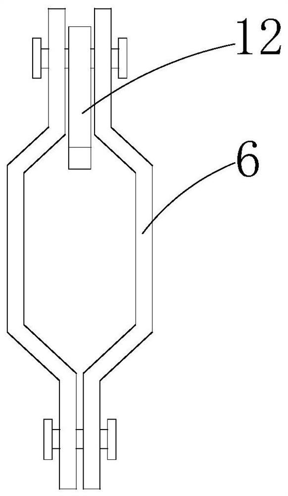
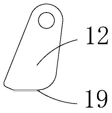
The invention discloses a tin plating tool and relates to the technical field of tin-plated part production. The tin plating tool comprises a working table. A tin-plated part is placed on the upper surface of the working table. Two pressing mechanisms distributed symmetrically are fixedly connected to the upper surface of the working table. Each pressing mechanism comprises a supporting plate, installing blocks, a rotating plate, a concave plate, a handle, a lifting block, a clamping block, a connecting block, a stretching mechanism, a U-shaped block, a thread rod, a nut and a pressing block,wherein the two installing blocks distributed symmetrically are fixedly welded to the bottom end of the supporting plate. According to the tin plating tool, by arranging the pressing mechanisms, the handles are pulled, and thus the tin-plated part can be pressed rapidly. The working efficiency of follow-up machining operation is improved. Moreover, the stretching mechanisms are arranged, people can assemble inserting connection blocks, thus the distance between each U-shaped block and the corresponding rotating plate can be changed, then the pressing blocks can fit with tin-plated parts of different sizes, and applicability of the device is improved.

Description

Technical field[0001]The invention relates to the technical field of production of tin-plated parts, in particular to a tin-plated tooling.Background technique[0002]Tin plating and its alloy is a kind of coating with good solderability and certain corrosion resistance, which is widely used in electronic components and printed circuit boards. In addition to the physical methods such as hot dipping and spraying, the methods of electroplating, immersion plating and electroless plating have been widely used in industry because of their simplicity and ease.[0003]The tin-plated parts need to be pressed and fixed during processing and production, such as drilling or welding. The existing pressing usually uses a threaded rod to rotate and drive the pressing block to move to realize the clamping of the workpiece. The clamping method requires continuous rotation of the screw to realize the clamping of the pressing block to the workpiece. The clamping process is inefficient and inconvenient to...

Claims


Application Information

Patent Timeline
Patent Type & Authority Applications(China)
IPC IPC(8): B25B11/00B23K37/04
CPCB23K37/0435B25B11/00B25B11/005
Inventor 刘欣鑫杨帅
Owner 刘欣鑫
Learn More