
Knee joint load reducing device

A load-relief device and knee joint technology, applied to knee joints, elbow joints, joint implants, etc., can solve problems such as high medical expenses, increased patient pain, and unsatisfactory results, so as to reduce surgical costs and avoid tendon injuries , the effect of delaying the operation time

Pending Publication Date: 2021-01-08
TONGJI HOSPITAL ATTACHED TO TONGJI MEDICAL COLLEGE HUAZHONG SCI TECH +1
View PDF0 Cites 0 Cited by
  • Summary
  • Abstract
  • Description
  • Claims
  • Application Information

AI Technical Summary

Problems solved by technology

However, the existing artificial joints used for replacement have a certain service life. When the prosthesis loosens and osteolysis occurs in the patient's body, joint revision surgery or knee joint replacement is required, which will not only increase the pain of the patient , and face high medical costs
[0004] In order to solve the above problems, medical researchers have been working hard to find various intervention measures or medical devices before performing artificial joint replacement surgery on patients, so as to relieve the pain symptoms of patients, delay the time of joint replacement, and improve the quality of life of patients. satisfactory progress

Method used


Image

  • Knee joint load reducing device
  • Knee joint load reducing device
  • Knee joint load reducing device

Examples


Embodiment Construction

[0020] The present invention will be further described in detail below with reference to the accompanying drawings and specific embodiments, but the embodiments should not be construed as limiting the present invention.

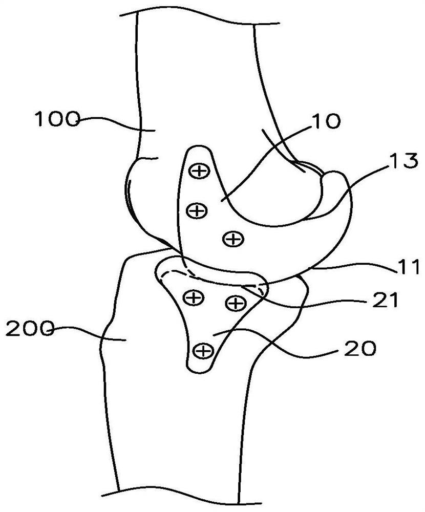
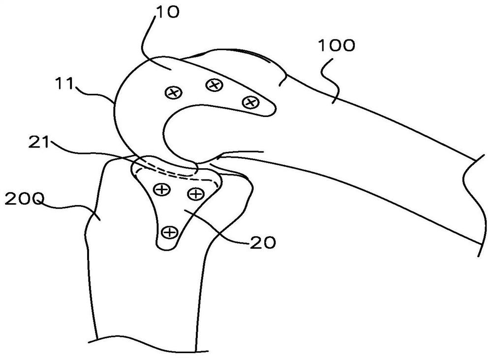
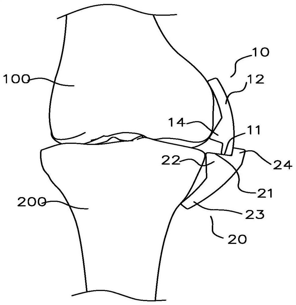
[0021] The knee joint unloading device described in this embodiment is implanted under the skin of the patient's knee joint, and is mainly used to assist in sharing the mechanical force transmitted from the patient's upper limb weight to the knee joint, so as to reduce friction and wear of the knee joint and relieve the patient's pain. and delaying the time of knee replacement in patients.

[0022] like Figures 1 to 4 As shown, the load relief device includes a first connector 10 and a second connector 20 . The first connector 10 is fixedly installed on the distal end of the femur 100 , specifically located on the distal end of the femur 100 near the knee joint, and a cam surface 11 is provided on the side of the first connector 10 facing the proximal end o...


PUM


Abstract

The invention discloses a knee joint load reducing device. The knee joint load reducing device is implanted under the skin of a knee joint of a patient and used for assisting in sharing part of mechanical force borne by the knee joint. The load reducing device comprises a first connecting piece and a second connecting piece. The first connecting piece is fixedly installed at the distal femur end,and a cam face is arranged on the side, facing the proximal tibia end, of the first connecting piece. The second connecting piece is fixedly installed at the proximal tibia end, and a groove face is arranged on the side, facing the distal femur end, of the second connecting piece. And the cam surface and the groove surface form a cam pair assembly, and are in butt-joint running fit with each other. The load reducing device is simple and exquisite in structure and convenient to mount and dismount, knee joint cartilage tissue contact abrasion can be reduced, tendon injury of the patient is avoided, and pain symptoms of the patient are relieved. Meanwhile, by implanting the load reducing device, the original knee joint structure of the patient can be reserved, and knee joint replacement operation time is delayed.

Description

technical field [0001] The present invention relates to an orthopaedic medical instrument implanted in a patient, in particular to a knee joint unloading device. Background technique [0002] The knee joint is the joint between the distal end of the femur and the proximal end of the tibia, which plays an important role in supporting the body weight of the human body. At present, knee arthritis has become a common degenerative disease among middle-aged and elderly people. The clinical symptoms are long-term knee pain and limited mobility, which greatly affects the quality of life of patients. During the movement of the knee joint, the distal end of the femur and the proximal end of the tibia are constantly rubbed and worn, causing pain and causing knee arthritis. [0003] When knee arthritis develops severely, patients have to undergo knee replacement surgery. However, the existing artificial joints used for replacement all have a certain service life. When the prosthesis l...

Claims


Application Information

Patent Timeline
Patent Type & Authority Applications(China)
IPC IPC(8): A61F2/38A61F2/30
CPCA61F2/3836A61F2/3872A61F2/30756A61F2002/30757
Inventor 肖骏朱皓齐大虎
Owner TONGJI HOSPITAL ATTACHED TO TONGJI MEDICAL COLLEGE HUAZHONG SCI TECH
Learn More