
Array substrate and display panel

A technology for array substrates and substrates, which can be used in instruments, nonlinear optics, optics, etc., and can solve the problems of lowering the image quality of display panels, high reflectivity, and increased reflectivity.

Inactive Publication Date: 2021-01-05
TCL CHINA STAR OPTOELECTRONICS TECH CO LTD
View PDF13 Cites 2 Cited by
  • Summary
  • Abstract
  • Description
  • Claims
  • Application Information

AI Technical Summary

Problems solved by technology

However, the metal in the TFT area reflects light strongly, and the reflectance of the light-transmitting area is also higher than that of the CF side facing outward, resulting in a significant increase in the reflectance of the display panel to ambient light, which will reduce the image quality of the display panel.

Method used


Image

  • Array substrate and display panel
  • Array substrate and display panel
  • Array substrate and display panel

Examples


Embodiment Construction

[0037]The technical solutions of the present invention will be clearly and completely described below in conjunction with the accompanying drawings in the present invention. Obviously, the described embodiments are only a part of the embodiments of the present invention, rather than all the embodiments. Based on the embodiments of the present invention, all other embodiments obtained by those skilled in the art without creative work shall fall within the protection scope of the present invention.

[0038]It should be noted that in the description of the present invention, it should be understood that the terms "upper", "lower", "front", "rear", "left", "right", "inner", "outer", etc. The indicated orientation or positional relationship is based on the orientation or positional relationship shown in the drawings, and is only for the convenience of describing the present invention and simplifying the description, rather than indicating or implying that the pointed device or element must ...


PUM

PropertyMeasurementUnit
thicknessaaaaaaaaaa
thicknessaaaaaaaaaa
thicknessaaaaaaaaaa

Abstract

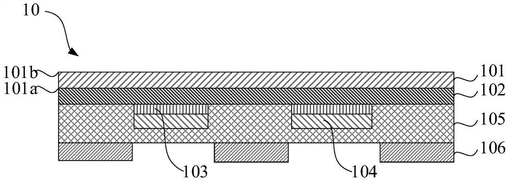
The invention provides an array substrate and a display panel. The array substrate comprises a substrate, a transparent insulating layer, a light absorption layer, a thin film transistor layer, a first protective layer and a color film layer. By arranging the light absorption layer in the array substrate, the problem that the reflectivity of the area where the thin film transistor layer is arranged is high is solved. Meanwhile, a whole transparent insulating layer is arranged between the substrate and the light absorption layer. According to the transparent insulating layer, on the one hand, the problem of high reflectivity of the corresponding area of the color film layer can be solved, and on the other hand, the adhesive force between the light absorption layer and the substrate can be enhanced, so the structure of the array substrate is more stable. Due to the fact that the transparent insulating layer and the light absorption layer are additionally arranged in the array substrate,the problem that a display panel emitting light from the side of the array substrate is large in reflectivity can be solved, the image quality of the display panel is improved, and the display panel can better meet the full screen requirement of the market.

Description

Technical field[0001]The present invention relates to the field of display technology, in particular to an array substrate and a display panel.Background technique[0002]Contrast is one of the important indicators for evaluating the image quality performance of liquid crystal display (LCD). In a real use scene, due to the influence of ambient light, the reflectivity of the display panel will affect the contrast of the picture, as shown below:[0003][0004]Lon / Loff Respectively indicate the brightness of the display panel in the bright state / dark state, RLIndicates the reflectivity of the display panel. Therefore, if you want to improve the contrast of the display panel, you can start from two aspects: 1. Increase the brightness of the display panel.on ; 2. Reduce the reflectivity R of the display panelL.[0005]At the same time, as the market's demand for borderless products grows, the TFT-side-out scheme is conducive to improving the module yield of four-sided borderless products. Howe...

Claims


Application Information

Patent Timeline
Patent Type & Authority Applications(China)
IPC IPC(8): G02F1/1333G02F1/1335G02F1/1362G02F1/1343
CPCG02F1/133345G02F1/1335G02F1/1362G02F1/136209G02F1/134309G02F1/133514G02F1/133502G02F1/133512G02F1/136222G02F1/1368G02F2201/50
Inventor 于晓平
Owner TCL CHINA STAR OPTOELECTRONICS TECH CO LTD
Learn More