
Optical light splitting device for receiving three wave bands through common window and application thereof

A spectroscopic device and three-band technology, applied in the field of optics, can solve the problems of non-compliance with portability, light weight, large volume, heavy weight, and limited application range, etc., and achieve the effect of light weight, small volume, and strong adaptability

Pending Publication Date: 2021-01-05
HUBEI HUAZHONG PHOTOELECTRIC SCI & TECH
View PDF4 Cites 5 Cited by
  • Summary
  • Abstract
  • Description
  • Claims
  • Application Information

AI Technical Summary

Problems solved by technology

Traditional camera products and ranging products often have large differences in structure and function. The two have completely different lens structures and optical path systems and are not compatible with each other. Larger obstacle
A simple solution is to directly assemble the traditional camera product and the distance measuring product on the same housing. The two are independent of each other, do not interfere with each other, and perform their respective functions. However, such products are often bulky and heavy. And it does not meet the development trend of portability and lightweight
[0003] In addition, existing ranging camera products often only have a single-channel camera function, and can only be used in environments with good lighting conditions, which greatly limits its application range

Method used


Image

  • Optical light splitting device for receiving three wave bands through common window and application thereof
  • Optical light splitting device for receiving three wave bands through common window and application thereof

Examples


Embodiment Construction

[0017] In order to enable those skilled in the art to fully understand the technical solutions and beneficial effects of the present invention, further description will be given below in conjunction with specific embodiments and accompanying drawings.

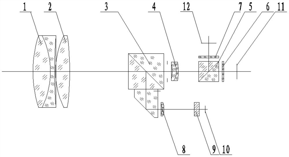
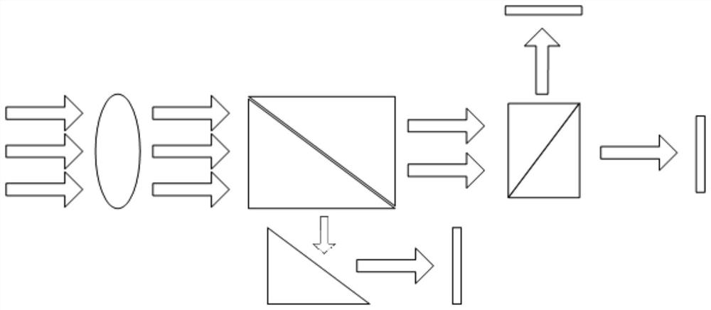
[0018] Such as Figure 1-2 The shown optical spectroscopic device for receiving three bands through a common window mainly includes an objective cemented lens 1 , an objective third lens 2 , a compound prism 3 , a focusing mirror 4 , and a beam splitting prism 5 arranged coaxially in sequence. Wherein the objective lens cemented lens 1 is formed by bonding a biconvex lens and a biconcave lens; the third lens 2 of the objective lens is a biconvex lens, and its front convex surface is close to the biconcave lens. Described composite prism 3 comprises two right-angled prisms of the same size and a right-angled trapezoidal prism, and the three are bonded together as shown in the figure; the dichroic prism 5 is formed by bonding two...


PUM

PropertyMeasurementUnit
Wavelengthaaaaaaaaaa

Abstract

The invention relates to an optical light splitting device for receiving three wave bands through a common window and application of the optical light splitting device in handheld, vehicle-mounted andairborne distance measurement camera shooting white light observation equipment and distance measurement double-path camera shooting equipment. The device comprises a common lens group, a composite prism, a beam splitter prism, an avalanche transistor detector, a near-infrared detector and a visible light detector. External light passes through the common lens group and is refracted into two paths of light by the composite prism, wherein one path of light enters the avalanche transistor detector, and the other path of light enters the beam splitter prism and then is refracted into two paths of light, and the two paths of light respectively enter the near-infrared detector and the visible light detector for imaging. The device is simple in structure, small in size and light in weight, achieves the three functions of distance measurement, visible light imaging and near-infrared light imaging at the same time, and is wide in application range and high in adaptability.

Description

technical field [0001] The invention relates to the field of optical technology, in particular to an optical spectroscopic device for receiving three bands through a common window and an application thereof. Background technique [0002] With the advancement of technology, multi-functional camera products have higher and higher requirements on function and integration, and multi-functional integrated miniaturized devices play an increasingly important role in practical applications. Traditional camera products and ranging products often have large differences in structure and function. The two have completely different lens structures and optical path systems and are not compatible with each other. Larger obstacle. A simple solution is to directly assemble the traditional camera product and the distance measuring product on the same housing. The two are independent of each other, do not interfere with each other, and perform their respective functions. However, such product...

Claims


Application Information

Patent Timeline
IPC IPC(8): G02B13/00G02B13/14G01C3/02
CPCG01C3/02G02B13/0055G02B13/006G02B13/0065G02B13/008G02B13/14
Inventor 鲜伟朱国强常大英张俊峰魏文彬高东海方勇强
Owner HUBEI HUAZHONG PHOTOELECTRIC SCI & TECH
Learn More