Drainage equipment of automatic heating furnace air preheater

A technology of air preheater and drainage equipment, which is applied in the direction of lighting and heating equipment, heat exchange equipment, steam/steam condenser, etc., and can solve the problem of affecting the normal operation of drainage equipment, unable to discharge condensed water, and filter debris that cannot be condensed water and other issues, to achieve the effect of complete functions, convenient viewing, and increased use of functions

Inactive Publication Date: 2021-01-05
SHANDONG LIANHUA NEW MATERIAL CO LTD
View PDF9 Cites 0 Cited by
  • Summary
  • Abstract
  • Description
  • Claims
  • Application Information

AI Technical Summary

Problems solved by technology

[0005] In order to solve the above-mentioned technical problems, the present invention provides a drainage device for the air preheater of the automatic heating furnace, so as to solve the problem that the existing drainage device for the air preheater of the automatic heating furnace cannot automatically discharge the condensed water and cannot clean the impurities in the condensed water. It is easy to affect the normal operation of the drainage equipment when the water is filtered and the power is cut off.

Method used


Image

  • Drainage equipment of automatic heating furnace air preheater
  • Drainage equipment of automatic heating furnace air preheater
  • Drainage equipment of automatic heating furnace air preheater

Examples


Embodiment

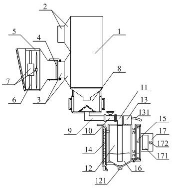
[0038] as attached figure 1 And attached figure 2 As shown, a drainage device for an air preheater of an automatic heating furnace includes a preheater main body 1, an air outlet pipe 2, an air inlet pipe 3, a limit frame 4, a detachable fan mounting frame structure 5, a support rod 6, and an inlet Fan 7, condensed water filter frame structure 8, left connecting pipe 9, switch valve 10, right connecting pipe 11, sealed tank 12, water pump 13, manual control frame structure 14, automatic water level detection frame structure 15, clean water 16 and Control box 17, the outlet pipe 2 is bolted to the upper left side of the preheater body 1; the intake pipe 3 is bolted to the lower left side of the preheater body 1; the limit frame 4 Welded on the left side of the air intake duct 3; the detachable fan mounting frame structure 5 is installed on the left side of the intake duct 3; the support rods 6 are respectively arranged on the inner side of the detachable fan mounting frame st...


PUM


Abstract

The invention provides drainage equipment of an automatic heating furnace air preheater. The equipment comprises a preheater main body, an air outlet pipeline, an air inlet pipeline, a limiting frame,a detachable fan mounting frame structure, a supporting rod, an air inlet fan, a condensate water filtering frame structure, a left side connecting pipe, a switch valve, a right side connecting pipe,a sealing tank, a water pump, a manual control frame structure, an automatic water level detection frame structure, clean water and a control box. The air outlet pipeline is in bolted connection withthe upper part of the left side of the preheater main body. The drainage equipment has the beneficial effects that through the arrangement of a water level sensor, a single-chip microcomputer, a water pump and an electromagnetic valve, the water level sensor detects the water level stored in the sealing tank and transmits a signal to the single-chip microcomputer, the single-chip microcomputer controls the water pump and the electromagnetic valve to act, and the water level on the inner side of the sealing tank can be conveniently and automatically controlled. The situation that the water level on the inner side of the sealing tank is too high or too low, and consequently the condensate water collecting effect or the sealing effect on the inner side of the preheater main body is affectedis prevented.

Description

technical field [0001] The invention belongs to the technical field of preheater auxiliary equipment, in particular to a drainage device for an air preheater of an automatic heating furnace. Background technique [0002] It is the heating surface that uses the flue gas in the flue at the end of the boiler to preheat the air before entering the boiler to a certain temperature through the internal heat sink. It is used to improve the heat exchange performance of the boiler and reduce energy consumption. Generally referred to as air preheater. [0003] However, the existing drainage equipment for the air preheater of the automatic heating furnace still has the problems that it cannot automatically discharge the condensed water, cannot filter the sundries in the condensed water, and the normal operation of the drainage equipment is easily affected when the power is cut off. [0004] Therefore, it is very necessary to invent a kind of drainage equipment of automatic heating fur...

Claims


Application Information

Patent Timeline
IPC IPC(8): F28B1/06F28B9/08F28B11/00F28F19/01F23L15/04
CPCF28B1/06F28B9/08F28B11/00F28F19/01F23L15/04Y02E20/34
Inventor 王旭忠赵现锋王静封彬彬
Owner SHANDONG LIANHUA NEW MATERIAL CO LTD
Why Eureka
Try Eureka