
Transfer pipet and its use

A liquid transfer device and liquid transfer technology, applied in the field of liquid transfer device, analysis or testing equipment, can solve the problems of automatic control, difficulty in adding liquid volume, affecting liquid transfer accuracy, etc.

Inactive Publication Date: 2007-09-05
上海浩源生物科技有限公司
View PDF3 Cites 19 Cited by
  • Summary
  • Abstract
  • Description
  • Claims
  • Application Information

AI Technical Summary

Problems solved by technology

Although this method can avoid cleaning the pushing body, due to the compressibility of the air, the pushing speed, pushing distance, etc. will be affected by the expansion and contraction of the air volume, making it difficult to automatically control the volume of liquid added according to the pre-designed program, which directly affects the pipetting precision
Utilize air movement technology to obtain high pipetting accuracy, just like PCT international application WO99 / 26723A, need to use complex push-out mechanism, piston, motor and its driving mechanism, and need to design cleaning system or use disposable element (such as Tube head in contact with liquid) and the automatic replacement system of these components not only greatly increase the cost of manufacturing and using the product, but also increase the difficulty of maintenance due to the complex structure of the device

Method used


Image

  • Transfer pipet and its use
  • Transfer pipet and its use
  • Transfer pipet and its use

Examples


Embodiment 1

[0038] Example 1 Pipetting device 1

[0039] As shown in FIG. 1A, an exemplary pipetting device 1 is composed of containers 10, 11, 12, 13, 14, 15, 16, connecting pipes 20, 21, 22, 23, 24, 25, 26, a multi-directional valve 30, The liquid adding pump 40 and the liquid adding pipe 31 are constituted. Among them, the five valves of the multidirectional valve 30 are respectively connected to different experimental liquids in different containers 11, 12, 13, 14, 15 through experimental liquid connecting pipes 21, 22, 23, 24, 25. The reference signs of the experimental liquid connecting pipes are 21, 22, 23, 24, 25, respectively. The reference numerals of the containers are 11, 12, 13, 14, and 15 respectively. The sixth valve of the multi-directional valve 30 is connected with a liquid adding pipe 31 for liquid adding. The liquid adding pump 40 (the syringe liquid adding pump of Cavro Company is illustrated in the embodiment) and the communication channel of the multi-directional valve ...

Embodiment 2

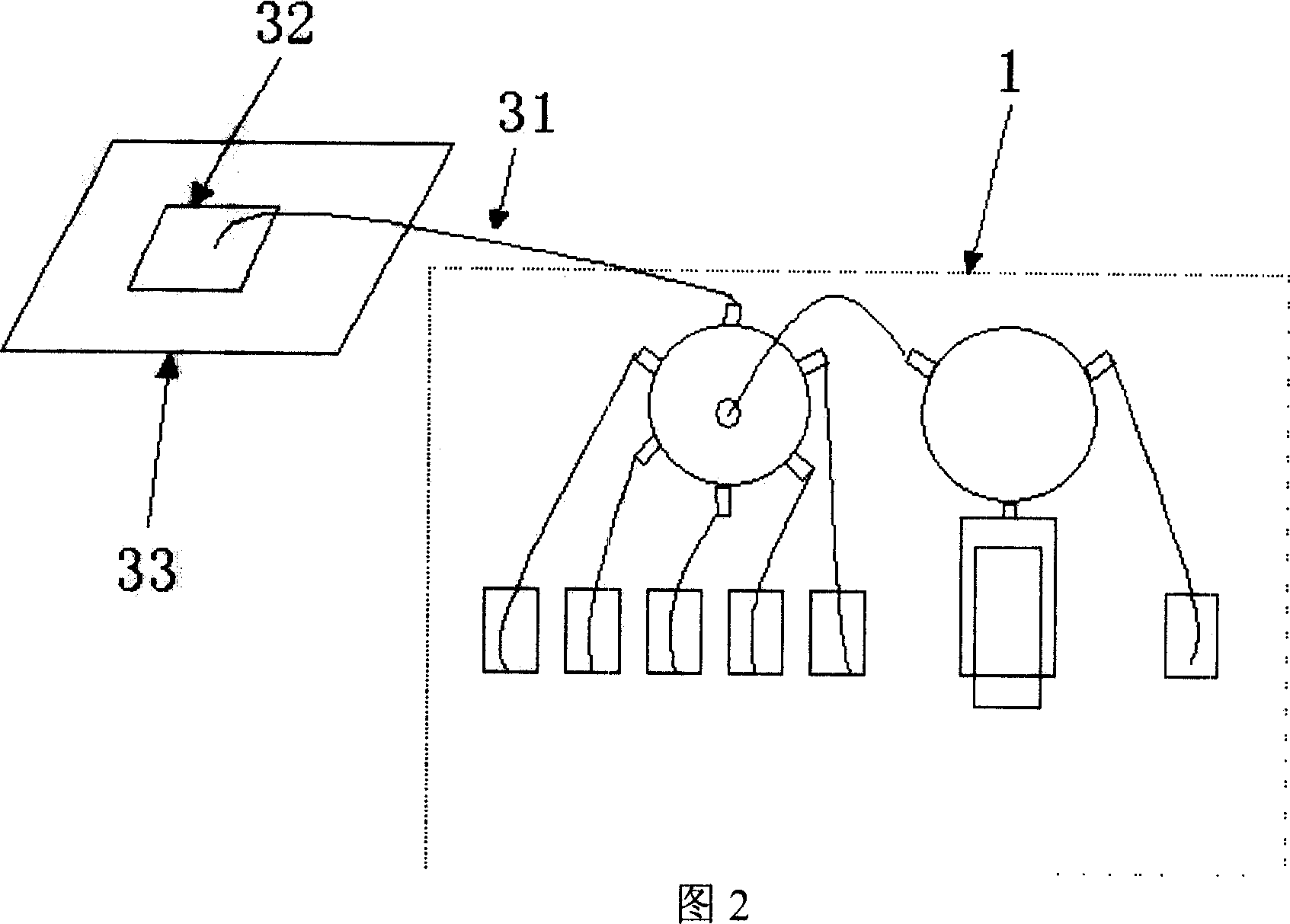
[0041] Example 2 Carrying out biological lattice spotting or adding samples to the PCR plate

[0042] As shown in FIG. 2, an automatically movable platform 33 is provided under the liquid adding pipe 31 of the pipetting device 1. A biochip base 32 or a 96-well PCR plate 32 can be placed on the platform 33. The automatic moving platform 33 is precisely controlled to move the positions or holes on the different substrates 32 to the liquid adding pipe 31, and the micro liquid will be accurately added to the positions or holes by the liquid adding pipe 31.

Embodiment 3

[0043] Example 3 PCR instrument

[0044] As shown in FIG. 3, an exemplary PCR machine is composed of a pipetting device 1, a platform 33, a PCR plate 32, a rotating robot 34, and a thermal cycler 35. Among them, an automatically movable platform 33 is arranged under the liquid addition tube 31 of the pipetting device 1, and a 96-well PCR plate 32 is placed on the platform. The automatic moving platform 33 is precisely controlled to move different holes under the liquid adding pipe 31, and the micro liquid will be accurately added to the holes by the liquid adding pipe 31. The PCR plate 32 can be moved to the thermal cycler 35 (such as the PTC-100 thermal cycler of Biorad) by rotating the robot hand 34 (for example, the rotary actuator linear acuator product of Oriental Motor Company) for PCR.


PUM

PropertyMeasurementUnit
diameteraaaaaaaaaa
densityaaaaaaaaaa

Abstract

A liquid transfer device for sucking the experimental liquid and distributing it to analyzing or testing apparatus has a pump unit, a connection unit and the cleaning liquid, which can be filled in said connection unit by pump unit and then be driven to move the experimental liquid in connection unit without mixing with experimental liquid. Its application, its operation method, and the analyzing and testing apparatus containing the liquid transfer device are also disclosed.

Description

Technical field [0001] The present invention belongs to the technical field of biological testing. Specifically, the present invention relates to a pipetting device in biological analysis or testing equipment, which can accurately distribute trace reagent liquid to the analysis or testing equipment, and is particularly suitable for transferring different types of trace reagents. The liquid does not contaminate each other. The pipetting device of the present invention can be widely used in sample analysis or testing in the fields of biology, immunology, medicine and the like. In addition, the present invention also relates to a method for applying the pipetting device for pipetting operations, and analysis or testing equipment including the pipetting device, such as a PCR machine, a biological spotting instrument, and the like. Background technique [0002] In a large number of clinical experiments and laboratory experiments in biology, immunology, medicine and other fields, accur...

Claims


Application Information

Patent Timeline
Patent Type & Authority Applications(China)
IPC IPC(8): B01L3/02G01N35/10
Inventor 袁石
Owner 上海浩源生物科技有限公司
Learn More