Eureka AIR delivers breakthrough ideas for toughest innovation challenges, trusted by R&D personnel around the world.

Methanol fuel injector structure

A technology of fuel injector and methanol, which is applied in the field of common rail electronically controlled gasoline engine to use methanol fuel and methanol injector structure, which can solve the problems of reduced flow rate of fuel injector, engine misfire, and increase of valve core moving resistance, etc.

Pending Publication Date: 2021-01-05
广东沛宇系统技术有限公司
View PDF0 Cites 0 Cited by
  • Summary
  • Abstract
  • Description
  • Claims
  • Application Information

AI Technical Summary

Problems solved by technology

Methanol injector is used as an actuator directly in contact with methanol fuel. Due to long-time immersion in methanol, the sediment in methanol will increase the movement resistance of the spool, and finally reduce the movement distance of the spool and the flow rate of the injector. Blockage, which in turn leads to sporadic engine misfires
[0003] A large number of methanol vehicles have been put into use in some parts of the country. The existing electronically controlled gasoline injector structure directly modifies the injection flow and is used for electronically controlled methanol injection. Because the working environment of the methanol injector is relatively harsh, the injector is relatively easy damage, resulting in a significantly higher cost of use

Method used


Image

  • Methanol fuel injector structure
  • Methanol fuel injector structure
  • Methanol fuel injector structure

Examples


Embodiment Construction

[0024] In order to make the object, technical solution and advantages of the present invention clearer, the present invention will be further described in detail below in conjunction with the accompanying drawings and specific implementation methods. It should be understood that the specific embodiments described here are only used to explain the present invention, and do not limit the protection scope of the present invention.

[0025] It should be noted that when an element is referred to as being “disposed on” or “fixed on” another element, it may be directly on another element or there may be an intervening element. When an element is referred to as being "fixed on" another element, or "fixedly connected" to another element, it may be detachably fixed or non-detachably fixed therebetween. When an element is referred to as being "connected" or "rotatably connected" to another element, it can be directly connected to the other element or intervening elements may also be pres...


PUM


Abstract

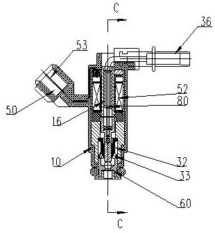
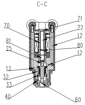
The invention relates to a methanol fuel injector structure. The methanol fuel injector structure comprises a shell, a valve element, a retainer and a valve seat; a fuel flowing channel is defined bythe shell; the valve seat is arranged at the bottom end of the shell; a guide hole is formed in the middle position of the retainer; the retainer is arranged in the flowing channel; the outer side wall of the valve element is in sliding fit with the guide hole so as to divide the flow channel into a first channel and a second channel close to the valve seat; the second channel is used for introducing methanol; and the first channel is used for introducing compressed gas with the same pressure as methanol. According to the methanol fuel injector structure, through matching between the valve element and the guide hole of the retainer, the valve element moves up and down along with an excitation signal when a methanol fuel injector works, the guide hole plays an accurate guide role, methanolforms a film in a gap under the action of pressure, the air pressure in the first channel is as same as the pressure of the methanol, the methanol cannot enter the first channel, and therefore, the situation that the methanol enters the valve element to gradually form colloid to enable the valve element fails to work is avoided.

Description

technical field [0001] The invention relates to the technical field of fuel injectors, in particular to a structure of a methanol fuel injector, which is suitable for changing a common-rail electronically controlled gasoline engine to use methanol fuel. Background technique [0002] Because the cost of methanol is much lower than that of gasoline, methanol vehicles came into being. As the name suggests, methanol vehicles use methanol as the vehicle fuel. The raw materials for methanol refining are usually natural gas, low-quality coal, etc., and methanol fuel is easily polluted and reacts with other media to produce deposits. Therefore, the quality of methanol fuel currently varies greatly, and there are more impurities in methanol than in gasoline. Methanol injector is used as an actuator directly in contact with methanol fuel. Due to long-time immersion in methanol, the sediment in methanol will increase the movement resistance of the spool, and finally reduce the movement...

Claims


Application Information

Patent Timeline
IPC IPC(8): F02M61/04F02M51/06F02M61/16F02M61/18
CPCF02M61/04F02M51/061F02M61/16F02M61/18
Inventor 林小东梁耀桓左卓均覃志佳
Owner 广东沛宇系统技术有限公司
Why Eureka
Eureka Blog
Learn More