A wafer etching back grinder

A back-grinding and grinding machine technology, applied in grinding machine tools, grinding devices, manufacturing tools, etc., can solve the problems of wafer precision decline and impact, etc.

Inactive Publication Date: 2021-08-10
车艾建
View PDF6 Cites 0 Cited by
  • Summary
  • Abstract
  • Description
  • Claims
  • Application Information

AI Technical Summary

Problems solved by technology

[0005] In order to solve the above technology, when the disc and the laser cooperate with each other to vibrate and polish the wafer, the repeated vibration will cause some wafers with low adhesion to produce slight displacement vibration, and the subtle vibration of the wafer during the grinding process is related to the The high-temperature diffraction generated during laser irradiation can easily affect the high-temperature diffraction area to the position that does not require grinding, resulting in a decrease in wafer precision

Method used


Image

  • A wafer etching back grinder
  • A wafer etching back grinder
  • A wafer etching back grinder

Examples


Embodiment 1

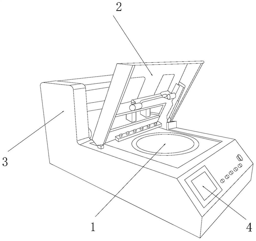
[0025] as attached figure 1 to attach Figure 5 Shown:

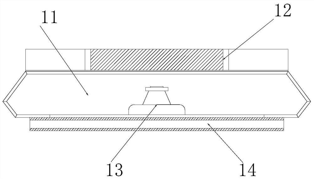
[0026] The present invention provides a wafer etching backside grinding machine, the structure of which includes a grinding mechanism 1, a cover plate 2, an equipment base 3, and a control panel 4. The grinding mechanism 1 is embedded and installed on the right upper end surface of the equipment base 3. The cover plate 2 is engaged and connected with the equipment seat 3, and the control panel 4 is fixedly mounted on the right end surface of the equipment seat 3; the grinding mechanism 1 includes a vacuum tank 11, an installation mechanism 12, a grinder 13, a sliding Rail 14, the vacuum tank 11 is inlaid directly above the slide rail 14, the installation mechanism 12 is inlaid and mounted directly above the grinder 13, and the grinder 13 is movably mounted on the slide rail 14 Above, the slide rail 14 is installed directly below the grinder 13 by welding.

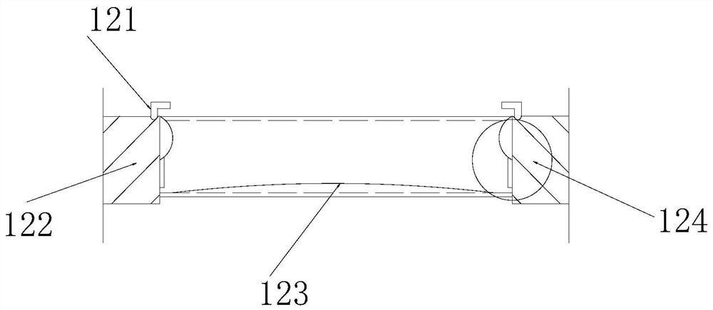
[0027] Wherein, the installation mechanism 12 includes a lock...

Embodiment 2

[0033] as attached Figure 6 to attach Figure 7As shown: the grinder 13 includes a heat insulation mechanism 131, a radiation port 132, a heat conduction block 133, a limiting plate 134, and an extension tube 135. The heat insulation mechanism 131 is embedded and installed directly above the radiation port 132, and the radiation The lateral outer end surface of the mouth 132 is inlaid and connected with the heat conduction block 133, and the heat conduction block 133 is symmetrically installed on the left and right sides of the upper end of the limit plate 134, and the limit plate 134 is embedded and installed directly above the extension tube 135, so that The extension tube 135 is nested and installed on the inner end surface of the grinder 13, and the connection end surface of the heat insulation mechanism 131 and the radiation port 132 is provided with an embedded tube. By limiting the area of ​​laser temperature diffraction, the grinding problem can be effectively solved....


PUM


Abstract

The invention discloses a wafer etching back grinder, the structure of which includes a grinding mechanism, a cover plate, an equipment seat, and a control panel. , the control panel is fixedly mounted on the right side of the equipment seat. When installing the wafer, the wafer can be squeezed into the ring-shaped plane formed by the rubber block, and the clamp formed by the movable plate and the flexible block The corner intercepts the wafer, and when the wafer squeezes the rubber block, its inner contour will be deformed with the extrusion and the support of the second rubber block, forming a wrapping shape on the lateral outer contour of the wafer .

Description

technical field [0001] The invention belongs to the field of wafer etching, and more specifically relates to a wafer etching back grinding machine. Background technique [0002] Wafer etching back grinding machine is a kind of laser and placement plate slightly vibrated and matched with the calculation results of network interruption to grind the thickness of the wafer, and the thickness of the wafer can be changed by grinding the wafer to increase the thickness of the wafer. precision. [0003] Based on the discovery of the above inventors, the existing methods mainly have the following disadvantages. For example, when the wafer is placed on the plate and the laser is vibrated and polished, the repeated vibration will cause a small part of the wafer with a low degree of adhesion. Displacement vibration, and the fine vibration of the wafer during the grinding process and the high-temperature diffraction generated by laser irradiation can easily cause the high-temperature di...

Claims


Application Information

Patent Timeline
Patent Type & Authority Patents(China)
IPC IPC(8): B24B37/10B24B37/34B24B37/30H01L21/67
CPCB24B37/10B24B37/30B24B37/34H01L21/67092
Inventor 李善龙
Owner 车艾建
Why Eureka
Try Eureka