A kind of mandrel clamp and its cooling method

A mandrel and fixture technology, used in manufacturing tools, glass manufacturing equipment, glass production, etc., can solve the problems of thermal deformation of the fixture, stuck bearings supporting the rotating shaft, and difficulty in the autobiography of the clamping components, so as to reduce the temperature, avoid the grilled effect

Active Publication Date: 2016-03-30
ZHEJIANG FUTONG OPTICAL FIBER TECH +1
View PDF4 Cites 0 Cited by
  • Summary
  • Abstract
  • Description
  • Claims
  • Application Information

AI Technical Summary

Problems solved by technology

[0004] In the process of depositing optical fiber preform, in order to prevent cracking at the joint between the loose body and the core rod due to excessive temperature gradient, a tail light is generally installed at the joint position of the loose body and the mandrel, and the tail light follows the main blowtorch Move left and right. During the process of loose body deposition, the taillight will burn to a distance of 80mm from the mandrel clamp. The taillight will be heated by the oxyhydrogen flame. The radiant heat of the oxyhydrogen flame and the heat transfer of the mandrel will cause the fixture to heat Deformation, the lubricating oil or lubricant in the clamping assembly will be chemically decomposed under the action of high temperature, which will cause the bearing supporting the rotating shaft to be stuck, and the clamping assembly will have difficulty in self-propagation

Method used


Image

  • A kind of mandrel clamp and its cooling method
  • A kind of mandrel clamp and its cooling method

Examples


Embodiment Construction

[0023] The core of the present invention is to provide a mandrel clamp to prevent the lubricating oil in the clamping assembly from decomposing and evaporating due to heat, so as to ensure that the rotating shaft can rotate freely and avoid the phenomenon of the rotating shaft being stuck.

[0024] In order to enable those skilled in the art to better understand the solution of the present invention, the present invention will be further described in detail below in conjunction with the accompanying drawings and specific embodiments.

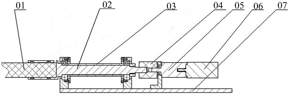
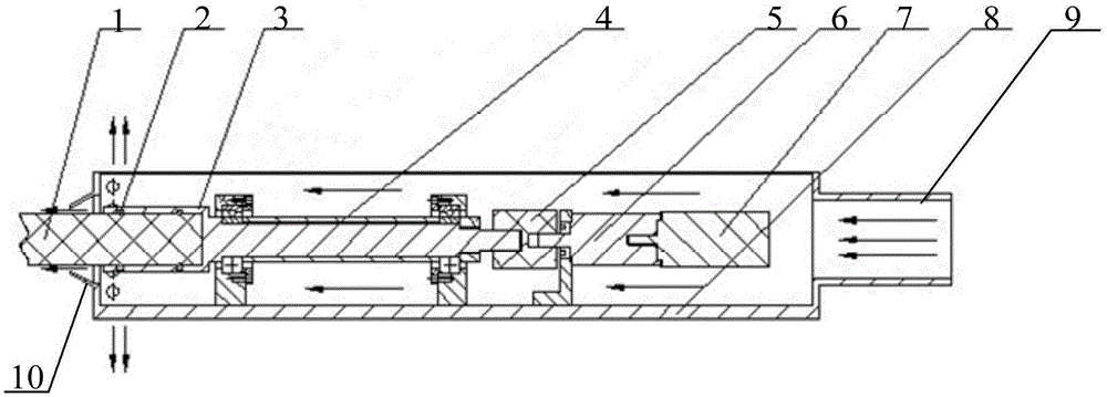
[0025] Please refer to figure 2 , figure 2 It is a partial structural cross-sectional view of the mandrel clamp provided in the embodiment of the present invention.

[0026] The mandrel clamp provided in the embodiment of the present invention is mainly used in the preparation process of the optical fiber preform, especially in the process of preparing the outer cladding of the optical fiber preform by the OVD method. Two clamping components...


PUM


Abstract

The invention relates to a core rod clamp for an optical fiber preform preparation process, which comprises two clamping components which are arranged symmetrically and used for respectively clamping both ends of a core rod, wherein each clamping component comprises a mounting shell arranged on a support seat, a frustum-shaped air deflector and an air supply outlet; one end of the mounting shell adjacent to a rear lamp is provided with a through hole through which the core rod can penetrate; the frustum-shaped air deflector is arranged on the outer edge of the through hole; the air supply outlet is arranged at one end of the mounting shell away from the rear lamp and used for supplying air to the inside of the mounting shell; and the big end of the frustum-shaped air deflector is fixedly connected with the mounting shell. The core rod clamp can effectively prevent rear lamp flame from roasting the mounting shell and rotating shaft, so the temperature in the rotating shaft and mounting shell is lowered, thereby preventing the lubricating oil and lubricant in the clamping components from being decomposed or evaporated by high temperature, and further providing reliable guaranty for flexible rotation of the rotating shaft. The invention also relates to a method for cooling the core rod clamp.

Description

technical field [0001] The invention relates to the technical field of optical fiber preparation, in particular to a core rod clamp used in the process of preparing an optical fiber preform rod and a cooling method for the core rod clamp. Background technique [0002] In the process of using OVD (Outside Vapour Deposition) method to manufacture the outer cladding of the optical fiber preform, it is necessary to uniformly deposit the silica dust after the high-temperature hydrolysis reaction on the core rod, so we need to use the core rod clamp to hold the core rod Both ends are fixed and allowed to rotate on its own axis. [0003] Please refer to figure 1 , figure 1 It is a schematic structural diagram of the clamping assembly of the current mandrel clamp. The mandrel clamp includes a clamping assembly symmetrically arranged and used to clamp both ends of the mandrel 01. The clamping assembly includes a mounting shell 07 (not all shown), and The servo motor 06, the reduce...

Claims


Application Information

Patent Timeline
Patent Type & Authority Patents(China)
IPC IPC(8): C03B37/018
CPCY02P40/57
Inventor 董瑞洪杨军勇章海峰陈坚盾
Owner ZHEJIANG FUTONG OPTICAL FIBER TECH
Why Eureka
Try Eureka