Intelligent air-jet textile machine sewing machine
A technology of textile machines and edge lockers, which is applied in textiles, fabric edge trimming, textiles, and papermaking. It can solve problems such as bottlenecks in production efficiency and inability to meet the maximum speed of vehicles, and achieve the effects of easy replacement and guaranteed combination reliability.
- Summary
- Abstract
- Description
- Claims
- Application Information
AI Technical Summary
Problems solved by technology
Method used
Image

Examples
Embodiment 1
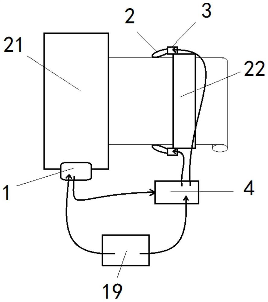
[0017] according to figure 1 , figure 2 , image 3 , Figure 4 As shown in the figure, an intelligent air-jet textile machine 21 edge locker includes a PLC controller 1 for controlling the work of the air-jet textile machine 21, and also includes: a heating head 2, and the heating head 2 is arranged on the The two sides of the discharge port 22 of the jet textile machine 21; the power supply module 4, the output end of the power supply module 4 is electrically connected with the heating head 2, and the input end of the power supply module 4 is connected with the power supply 19; the power supply module 4. The communication port is electrically connected to the signal output port of the PLC controller 1, and is used for outputting a constant current to the output terminal according to the signal of the PLC controller 1.
[0018] In the above setting, the heating head 2 is realized by a plastic heating wire. Therefore, on the basis of the fixed seat 3, the heating head 2 is ...
Embodiment 2
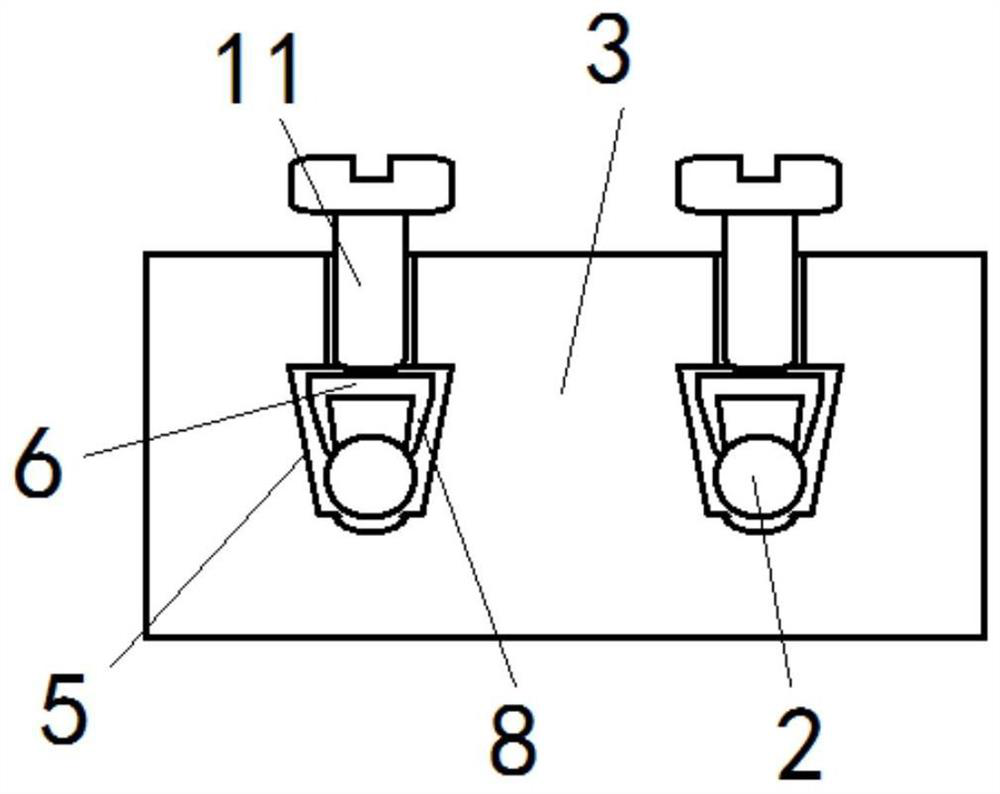
[0020] The fixed seat 3 is provided with a channel 5 running through both sides, and an electrical conductor 6 is arranged in the channel 5. The input end of the heating head 2 extends to the inside of the channel 5 through any end of the fixed seat 3, and is electrically connected to the electrical conductor 6 ; the end of the electrical conductor 6 away from the heating head 2 is electrically connected to the output end of the power module 4 through a high temperature wire 7 .
[0021] In this setting, the fixed seat 3 is made of high temperature resistant ceramics, and the heating head 2 and the electrical conductor 6 in the fixed seat 3 are detachably connected, so as to meet the requirements of different positions and different materials for edge locking, while the electrical conductor 6 It is connected between the high temperature wire 7 and the heating head 2 as an intermediate piece, which not only plays a role of heat insulation, but also facilitates the replacement of...
Embodiment 3
[0023] The cross-section of the channel 5 is arranged in an inverted trapezoid shape, and the bottom of the cross-section of the channel 5 is a circular groove structure; the top of the electrical conductor 6 is a flat plate structure, and is arranged in parallel with the top of the channel 5; The area near both ends of the side is respectively provided with a folded edge 8 that is folded downward, and the bottom end of the folded edge 8 is arranged with serrated teeth 9; There is a fixing hole penetrating to the outside of the fixing base 3 , a fixing screw 11 is fitted in the fixing hole, and the outer end of the fixing screw 11 is inclined toward the corresponding end of the channel 5 .
[0024] In the above-mentioned setting, the electric conductor 6 is pressed by rotating the fixing screw 11, thereby forcing the electric conductor 6 to apply pressure to the heating head 2 and the high-temperature wire 7 to the side wall direction of the channel 5, while the folding edge 8 ...
PUM
 Abstract
Description
Claims
Application Information
 - R&D
- Intellectual Property
- Life Sciences
- Materials
- Tech Scout
- Unparalleled Data Quality
- Higher Quality Content
- 60% Fewer Hallucinations
Browse by: Latest US Patents, China's latest patents, Technical Efficacy Thesaurus, Application Domain, Technology Topic, Popular Technical Reports.
© 2025 PatSnap. All rights reserved.Legal|Privacy policy|Modern Slavery Act Transparency Statement|Sitemap|About US| Contact US: help@patsnap.com