
Automatic machining equipment for conical fire grate

A processing equipment and grate technology, which is applied in the field of automatic processing equipment, can solve the problems of increasing the contact area between air and fuel, manual operation, labor intensity, and insufficient combustion, etc., to reduce surface temperature and tool wear, and improve work efficiency , The effect of low maintenance cost

Pending Publication Date: 2021-01-05
东莞市优伟机电科技有限公司
View PDF0 Cites 6 Cited by
  • Summary
  • Abstract
  • Description
  • Claims
  • Application Information

AI Technical Summary

Problems solved by technology

[0003] The existing non-standard cone grate processing equipment, common problems are: limited by the manufacturing process, the traditional grate shape has multiple flat grates, but the flat grate is easy to cause fuel accumulation, insufficient combustion, and black smoke , The problem of manual operation is labor-intensive, so the appearance of the combustion furnace with conical grate effectively solves the problem of increasing the contact area between air and fuel, and the fuel is evenly dispersed, and the combustion is uniform and it is not easy to generate black smoke

Method used


Image

  • Automatic machining equipment for conical fire grate
  • Automatic machining equipment for conical fire grate
  • Automatic machining equipment for conical fire grate

Examples


Embodiment Construction

[0027]The following will clearly and completely describe the technical solutions in the embodiments of the present invention with reference to the accompanying drawings in the embodiments of the present invention. Obviously, the described embodiments are only some, not all, embodiments of the present invention.

[0028] In the description of the present invention, unless otherwise stated, the meaning of "plurality" is two or more; the terms "upper", "lower", "left", "right", "inner", "outer" , "front end", "rear end", "head", "tail", etc. indicate the orientation or positional relationship based on the orientation or positional relationship shown in the drawings, and are only for the convenience of describing the present invention and simplifying the description, rather than Indicates or implies that the device or element referred to must have a particular orientation, be constructed and operate in a particular orientation, and therefore should not be construed as limiting the ...


PUM


Abstract

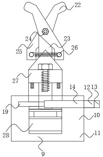
The invention discloses automatic machining equipment for a conical fire grate, and relates to the technical field of non-standard cone machining. The automatic machining equipment specifically comprises a base, a gap ratchet wheel mechanism, a multi-angle polishing mechanism, a grooved pulley punching mechanism and a lifting discharging mechanism; a motor is arranged on one side of the base; andthe lifting discharging mechanism is arranged on the side, away from the multi-angle polishing mechanism, of the top end of a movable beam. According to the automatic machining equipment for the conical fire grate, through arrangement of a composite clamp mechanism, it is guaranteed that a workpiece can rotate intermittently to be matched with a punch to complete punching operation while the conical workpiece is clamped, and a clamping rod is driven by a transmission rod to complete clamping of the workpiece; through arrangement of a reset spring, a clamping mechanism can rebound quickly, thehigher working efficiency is achieved, the shape design that the top of the clamping rod is attached to the cone enables the mechanism to have the higher clamping force, the design that a driven gearis matched with a cantilever rod enables a clamp to intermittently move at a controllable rotating angle, and machining in the subsequent punching link is facilitated.

Description

technical field [0001] The invention relates to the technical field of non-standard cone processing, in particular to an automatic processing equipment for conical grate. Background technique [0002] The grate is a component that stacks solid fuel in a boiler or industrial furnace and makes it burn effectively. The grate pieces are usually made of cast iron. After assembly, the necessary ventilation gaps are maintained between the pieces and the pieces are often adjusted under the grate. The air volume is divided into a ventilation room so that the air enters the fuel layer through the gap for combustion, and the burnt ash is discharged manually or mechanically. [0003] The existing non-standard cone grate processing equipment, common problems are: limited by the manufacturing process, the traditional grate shape has multiple flat grates, but the flat grate is easy to cause fuel accumulation, insufficient combustion, and black smoke 1. The labor-intensive problem of manua...

Claims


Application Information

Patent Timeline
IPC IPC(8): B21D28/32B21D43/00B21D37/18B24B21/00B24B47/16B24B47/26B24B21/18
CPCB21D28/32B21D37/18B21D43/003B24B21/00B24B21/18B24B47/16B24B47/26
Inventor 李路云张柱烜杨宇民
Owner 东莞市优伟机电科技有限公司
Learn More