
Sweeping robot

A sweeping robot and fan technology, which is applied in the field of sweeping robots, can solve the problems of reduced air volume, small size, and short air outlet ducts, and achieve the effects of avoiding superimposed enlargement, length extension, and length extension

Pending Publication Date: 2021-01-05
NINGBO FUJIA IND
View PDF0 Cites 2 Cited by
  • Summary
  • Abstract
  • Description
  • Claims
  • Application Information

AI Technical Summary

Problems solved by technology

At present, most of the air outlet structures are relatively small in size, and the air outlet channel through which the air is discharged from the housing by the fan is short, and the air flowing in the air outlet channel will generate relatively large noise due to fluid vibration, and the operation of the fan itself will also generate noise. A lot of noise, the noise is even louder when the hatchback is superimposed
In the existing technology, the noise is reduced by extending the air duct, but the volume of the sweeping robot is also increased, which is not conducive to the principle of miniaturization of the machine
Although the air outlet in the form of a spiral can extend the air outlet and reduce noise without increasing the volume of the sweeping robot, but because the curved air outlet has been changing the flow direction of the air, the energy loss of the air If it is too large, it may even slow down the flow rate of the air, which will greatly reduce the air output per unit time and reduce the working efficiency of the sweeping robot.

Method used


Image

  • Sweeping robot
  • Sweeping robot
  • Sweeping robot

Examples


Embodiment 1

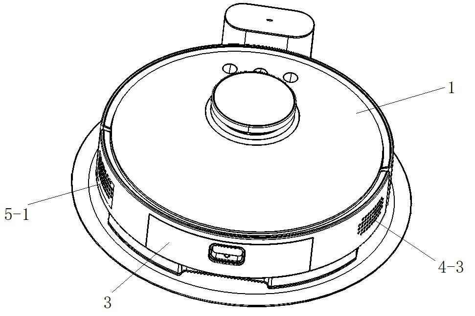
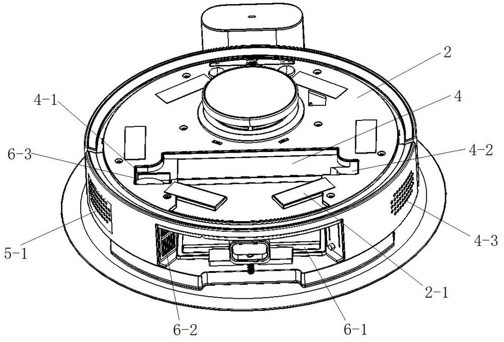
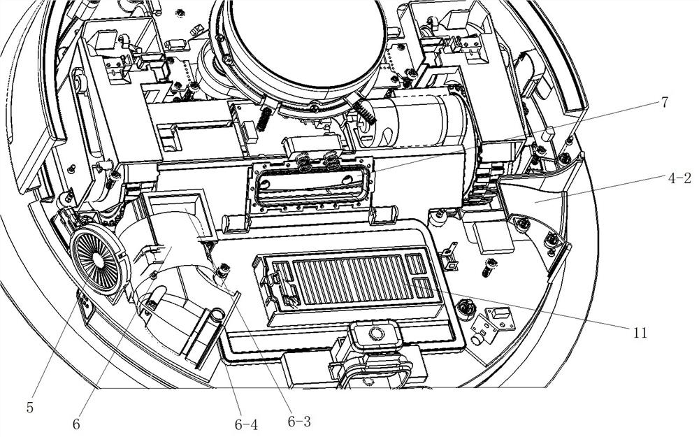
[0027] Such as Figure 1 to Figure 3As shown in , the sweeping robot in this embodiment includes a housing and a fan assembly arranged inside the housing, an air inlet structure and an air outlet structure. Encapsulated in the shell and can be dustproof and waterproof; the air intake structure includes the dust suction port 7 and the fan air intake channel 6-1, the dust suction port 7 connects the dust suction part at the bottom of the shell with the fan air intake channel 6-1, A dust box 3 and a filter 11 are arranged in the air inlet channel 6-1 of the fan, the dust box 3 is arranged in the space between the fan 6 and the air outlet 4-3 of the air duct, and a dust supply box is arranged on the side wall of the housing 3 The opening of the air inlet channel 6-1 of the fan in and out is conducive to the compact structure of the whole machine, and it is convenient to install or disassemble the dust box, and the installation or removal of the dust box will not interfere with oth...

Embodiment 2

[0032] Such as Figure 4 to Figure 5 As shown in , the sweeping robot in this embodiment includes a housing, a fan assembly arranged inside the housing, an air inlet structure and an air outlet structure, and a navigation radar 10. The housing is provided with a cover 1, which will The internal parts of the sweeping robot are enclosed in a housing and are dustproof and waterproof. The air intake structure includes a dust suction port 7, a dust suction channel 8 and an air intake channel 4-4 of the fan. 8 is provided with a dust box (not shown) and a filter 11, and the dust box enters and exits the dust suction channel 8 from the top of the housing. The fan assembly includes a fan 6. The fan 6 is adjacent to the inner wall of the housing. The two ends of the fan 6 are respectively provided with an air inlet and an air outlet. Both the air inlet and the air outlet of the fan are provided with sealing rings (not shown). The air inlet is connected with the air inlet channel 4-4,...


PUM


Abstract

The invention provides a sweeping robot which comprises a shell, a draught fan assembly, an air inlet structure and an air outlet structure, the draught fan assembly, the air inlet structure and the air outlet structure are arranged in the shell; the draught fan assembly comprises a draught fan, the air outlet structure comprises an air outlet channel and an air channel air outlet, and air is sucked in from the air inlet structure, passes through the draught fan, enters the air outlet structure and is finally exhausted from the air channel air outlet. The draught fan and the air channel air outlet are arranged on the two sides of the shell respectively, the air outlet channel is arranged between the fan and the air channel air outlet, and the draught fan is communicated with the air channel air outlet through the air outlet channel. According to the sweeping robot, the draught fan and the air channel air outlet are located in the two sides of the shell correspondingly, and superposition and amplification of noise are avoided; meanwhile, the air outlet channel is located between the draught fan and the air channel air outlet, the space between the draught fan and the two sides, where the air channel air outlet is located, of the shell is utilized, and the air outlet channel is prolonged on the premise that the size of the sweeping robot is not increased; and the length of the air outlet channel is increased, so that the noise generated when air flows in the air outlet channel is very low.

Description

technical field [0001] The invention relates to the technical field of cleaning household appliances, and more specifically relates to a sweeping robot. Background technique [0002] With the increasing intelligence of human life, the application of sweeping robots is becoming more and more common. It can automatically complete the cleaning of the ground under the control of artificial intelligence. The sweeping robot sucks the dust on the ground together with the air through the operation of its internal fan, and keeps the dust in the dust box, while the clean air is discharged through the air outlet structure. At present, most of the air outlet structures are relatively small in size, and the air outlet channel through which the air is discharged from the housing by the fan is short, and the air flowing in the air outlet channel will generate relatively large noise due to fluid vibration, and the operation of the fan itself will also generate noise. A lot of noise, the no...

Claims


Application Information

Patent Timeline
Patent Type & Authority Applications(China)
IPC IPC(8): A47L11/24A47L11/40F04D29/66
CPCA47L11/24A47L11/4094A47L11/40A47L11/4013F04D29/664F04D29/668A47L2201/00
Inventor 方剑强汪旭金璐丰王跃旦
Owner NINGBO FUJIA IND
Learn More