
Indoor building cold water replacement ventilation system and control method thereof

A technology for replacing ventilation and cold water. It is applied in ventilation systems, building components, air conditioning systems, etc. It can solve the problems of increasing air supply volume, increasing equipment investment, and difficulty in arranging diffusers, so as to avoid energy waste.

Pending Publication Date: 2021-01-01
XI'AN UNIVERSITY OF ARCHITECTURE AND TECHNOLOGY
View PDF0 Cites 1 Cited by
  • Summary
  • Abstract
  • Description
  • Claims
  • Application Information

AI Technical Summary

Problems solved by technology

At the same time, the existing replacement ventilation air supply method has always been accompanied by the problem that the temperature difference and air volume of the air supply are difficult to design. If the temperature difference of the air supply is small, the air supply volume needs to be increased, thereby increasing the number and size of diffusers. The equipment investment is increased, and the diffuser is difficult to arrange; if the temperature difference of the supply air is large, the temperature of the supply air will inevitably decrease, and the large temperature difference between the head and the feet is not conducive to the thermal comfort of the human body

Method used


Image

  • Indoor building cold water replacement ventilation system and control method thereof
  • Indoor building cold water replacement ventilation system and control method thereof
  • Indoor building cold water replacement ventilation system and control method thereof

Examples


Embodiment Construction

[0050] The present invention will be further described in detail below in conjunction with specific embodiments, which are explanations of the present invention rather than limitations.

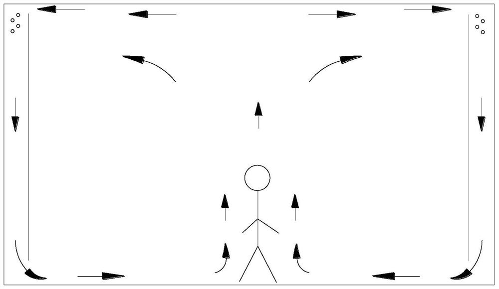
[0051] Such as figure 1 As shown, a cold water displacement ventilation system for an indoor building of the present invention, the indoor building is preset with airflow passages interpenetrating around the interior wall, and an airflow outlet 10 is opened below the airflow passage, and a movable airflow outlet is provided at the airflow outlet. baffle; the system includes a ventilation assembly and a chiller for preparing chilled water, the ventilation assembly includes a cold water coil 9 spirally installed on the top of the air flow channel, and a temperature sensor, a speed sensor and a controller set indoors; the speed sensor is set At the air outlet 10; one end of the cold water coil 9 is connected to the water outlet of the chiller through a chilled water valve, and the other end is c...


PUM


Abstract

The invention belongs to the technical field of indoor refrigeration, and particularly discloses an indoor building cold water replacement ventilation system and a control method. Airflow channels which communicate with one another are preset in an indoor building along the periphery of an indoor wall, airflow outlets are formed below the airflow channels, and movable baffles are arranged at the airflow outlets. The system comprises a ventilation assembly and a water chilling unit used for preparing chilled water, wherein the ventilation assembly comprises a cold water coil pipe spirally installed at the tops of the airflow channels, a temperature sensor, a speed sensor and a controller; the temperature sensor, the speed sensor and the controller are arranged indoors, and the speed sensoris arranged at the airflow outlets; one end of the cold water coil pipe is connected with a water outlet of the water chilling unit through a chilled water valve, and the other end of the cold water coil pipe is connected with a water inlet of the water chilling unit; and the temperature sensor, the speed sensor, the chilled water valve and the movable baffles are all connected with the controller, and the controller is used for controlling the opening size of the chilled water valve and the movable baffles. The upper space of a room is saved, and the ventilation efficiency and the thermal comfort of the human body can be effectively guaranteed.

Description

technical field [0001] The invention belongs to the technical field of indoor refrigeration, and in particular relates to an indoor building cold water replacement ventilation system and a control method thereof. Background technique [0002] In modern life, indoor air conditioning environment is becoming more and more important. The traditional mixed air supply has been difficult to meet people's needs for thermal comfort and indoor air quality. The most effective way is to quickly discharge indoor pollutants and loads, and send fresh air directly to people as much as possible. Compared with mixed air supply, displacement ventilation has higher ventilation efficiency, better air quality in the working area, and can effectively meet the thermal comfort of human body. Therefore, displacement ventilation is widely used in current air conditioning systems. [0003] In the existing displacement ventilation system, the wind processed by the air conditioning unit is powered by ...

Claims


Application Information

Patent Timeline
Patent Type & Authority Applications(China)
IPC IPC(8): F24F7/007F24F5/00F24F11/89F24F11/64E04B1/76
CPCF24F7/007F24F5/0007F24F11/89F24F11/64E04B1/76
Inventor 杨斌苏伟杨长青尹海国高然李安桂
Owner XI'AN UNIVERSITY OF ARCHITECTURE AND TECHNOLOGY
Learn More