
Multifunctional postprocessing support system

A support system and multi-functional technology, which is applied in the direction of charging system, combustion air/combustion-air treatment, fuel air filter, etc., can solve the problem of short service and maintenance cycle of post-processing devices, lack of dark space for parts, and inflexibility Adjustment and other issues to achieve the effect of prolonging the use and maintenance cycle, good protection, and compact structure

Pending Publication Date: 2021-01-01
GUANGXI YUCHAI MASCH CO LTD
View PDF0 Cites 0 Cited by
  • Summary
  • Abstract
  • Description
  • Claims
  • Application Information

AI Technical Summary

Problems solved by technology

[0002] The post-processing bracket is an important part to support and fix the post-processing. In the traditional design of the post-processing bracket, the bracket body is a flat plate with an enlarged area. It is supported on the top of the cylinder head by several columns, and the bracket and the cylinder head are in direct contact. The method is fixed, and the post-processing device and the bracket are also fixed by direct contact. The position of the post-processing device relative to the bracket is fixed and cannot be adjusted flexibly.
In addition, this hard connection arrangement does not take into account the impact of vibration on the parts of the post-processing device during use, resulting in a short maintenance period for the post-processing device, and does not play a good role in protecting the post-processing
At the same time, the body of the post-processing bracket has no other auxiliary functions, lacks space for parts to be turned secretly, and has a single function

Method used


Image

  • Multifunctional postprocessing support system
  • Multifunctional postprocessing support system
  • Multifunctional postprocessing support system

Examples


Embodiment Construction

[0029] A specific embodiment of the present invention will be described in detail below in conjunction with the accompanying drawings, but it should be understood that the protection scope of the present invention is not limited by the specific embodiment. It should be understood that the "up", "down", "left" and "right" directions mentioned in the following embodiments of the present invention are all based on the positions in the corresponding drawings. These words used to limit the direction are only for convenience of description, and do not mean to limit the specific technical solution of the present invention. Unless otherwise specified, the same reference numerals represent the same structure.

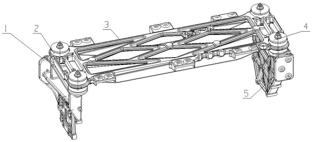
[0030] as attached figure 1 As shown, the main body of a multifunctional post-processing support system of the present invention is a concave structure, and is composed of three post-processing supports, rubber damping pads 2 and steel plate pads 4 to form a support main body, ...


PUM


Abstract

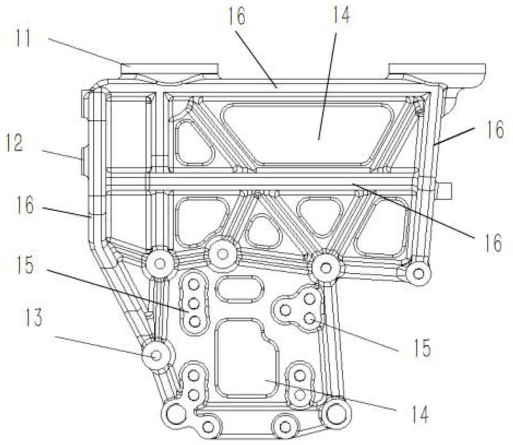
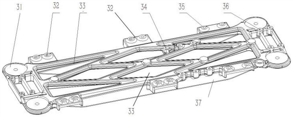
The invention discloses a multifunctional postprocessing support system. Three postprocessing supports, rubber anti-vibration pads and steel plate cushion blocks are combined into a main body, and a post-processor, a fuel filter and an air filtering system can be arranged in various positions by using one set of postprocessing support system, i.e., through mounting holes in a postprocessing support II and different mounting modes of the postprocessing support II, arrangement modes of various parts such as a postprocessing system, an air filtering system and a fuel filter can be achieved. In addition, through the mounting holes in the postprocessing support III, the arrangement mode of a fuel filtering system can be supplemented, the arrangement structural form is more diversified, the arrangement requirement of a whole machine is met, and an internal combustion engine is safer and has fewer troubles in the using process through the structure. Besides, according to the postprocessing supports, suspension anti-vibration pad mounting surfaces are arranged on the supports in advance, so that a flexible connection mode is formed between postprocessing parts and the supports, and damageto the strength of a postprocessing device due to vibration of an engine and a whole vehicle is reduced.

Description

technical field [0001] The invention relates to the technical field of internal combustion engine assembly, in particular to a multifunctional post-processing support system of an internal combustion engine. Background technique [0002] The post-processing bracket is an important part to support and fix the post-processing. In the traditional design of the post-processing bracket, the bracket body is a flat plate with an enlarged area. It is supported on the top of the cylinder head by several columns, and the bracket and the cylinder head are in direct contact. The method is fixed, and the post-processing device and the support are also fixed by direct contact. The position of the post-processing device relative to the support is fixed and cannot be adjusted flexibly. In addition, this hard connection arrangement does not take into account the impact of vibration on the parts of the post-processing device during use, resulting in a short service and maintenance period for ...

Claims


Application Information

Patent Timeline
Patent Type & Authority Applications(China)
IPC IPC(8): F01N13/18F02M35/04F02M37/00F16F15/08
CPCF01N13/18F02M35/048F02M37/0047F16F15/08
Inventor 王羽陈剑涛王仲统谢雄亮
Owner GUANGXI YUCHAI MASCH CO LTD
Learn More