
Steel plate bending machine

A technology of bending machine and steel plate, applied in the field of steel plate bending machine, can solve the problems of increasing labor time and strength, lifting of bending parts, affecting the quality of steel plate, etc., to improve the positioning effect, not easy to skew, improve The effect of work efficiency

Inactive Publication Date: 2021-01-01
安徽运杰机械设备制造有限公司
View PDF0 Cites 4 Cited by
  • Summary
  • Abstract
  • Description
  • Claims
  • Application Information

AI Technical Summary

Problems solved by technology

The traditional steel plate bending method has the following problems: 1. After placing the steel plate that needs to be bent, if it is not placed in place, it needs to be manually lifted and moved to adjust the position of the steel plate, which reduces work efficiency and increases labor. Working time and strength; 2. When the steel plate is bent, the two sides of the bending part are prone to warping, especially when the distance between the bending part and the two ends of the steel plate is long, which not only affects the quality of the steel plate after bending , and may also need to be reworked and corrected later, which also increases the time and intensity of manual work

Method used


Image

  • Steel plate bending machine
  • Steel plate bending machine
  • Steel plate bending machine

Examples


Embodiment Construction

[0027] Specific embodiments of the present invention will be described below in conjunction with the accompanying drawings.

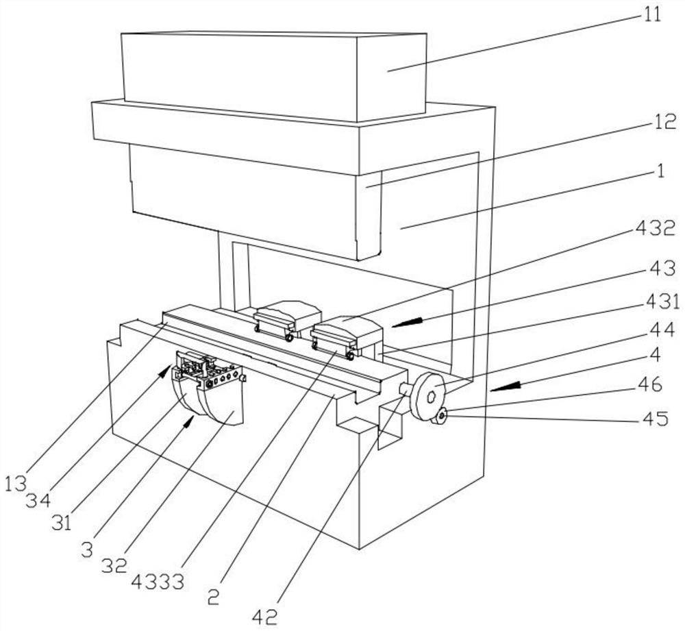
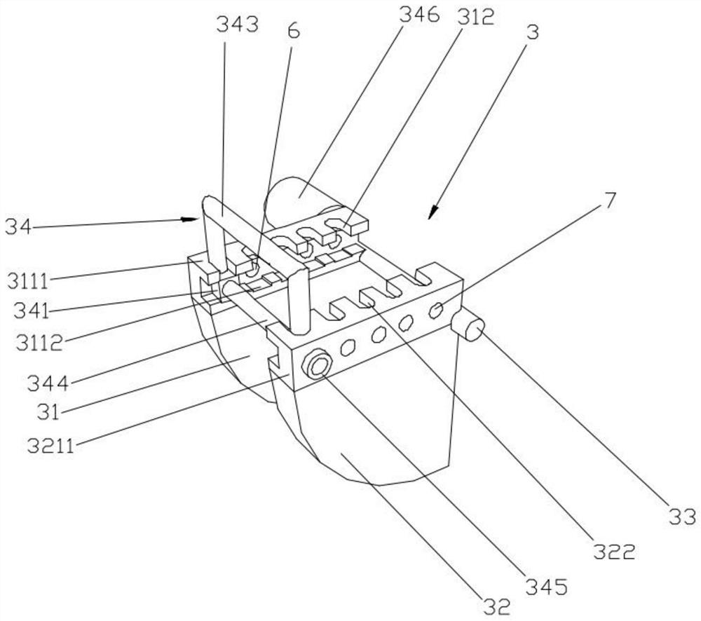
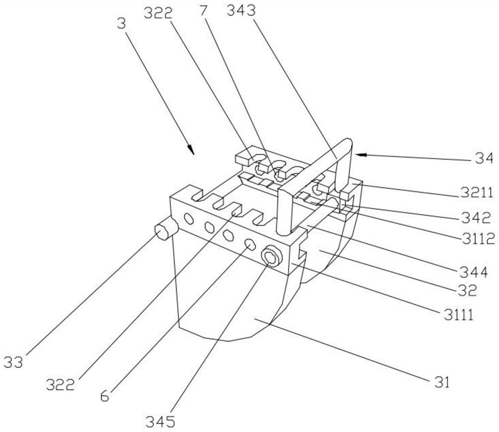
[0028] like Figure 1-9 As shown, it is a steel plate bending machine of this embodiment, including a bending machine body 1, a hydraulic cylinder 11 is arranged on the top of the bending machine body 1, and a bending upper knife die 12 is arranged on the piston rod of the hydraulic cylinder 11. , the bending machine body 1 is provided with a workbench 2 at a position corresponding to the bending upper die 12, and the top surface of the workbench 2 is provided with a knife groove 13 that is compatible with the bending upper die 12. The front and rear ends of the table 2 are respectively provided with a plate positioning rod device 3 and a plate anti-warping device 4. The plate positioning rod device 3 includes a left guide rotating plate 31 and a right guiding rotating plate 32 arranged in parallel and at intervals, and the left guiding rotating plate 3...


PUM


Abstract

The invention provides a steel plate bending machine, and relates to the technical field of plate bending equipment. The steel plate bending machine comprises a bending machine body, wherein a hydraulic cylinder is arranged at the top of the bending machine body; a bending upper cutting die is arranged on a piston rod of the hydraulic cylinder; a workbench is arranged at the position, corresponding to the bending upper cutting die, of the bending machine body; a cutter groove matched with the bending upper cutting die is formed in the top surface of the workbench; a plate positioning rod device and a plate anti-warping device are arranged at the front end and the rear end of the workbench respectively; the plate positioning rod device comprises a left guide rotating plate and a right guiderotating plate which are arranged in parallel at an interval; the left guide rotating plate and the right guide rotating plate are both in a fan shape; the left guide rotating plate and the right guide rotating plate are fixedly connected through a connecting shaft; and a left plate groove and a right plate groove are formed in the front end surface of the workbench. The steel plate bending machine has the advantages that the phenomenon that steel plates with different lengths are warped during bending can be avoided, the operation efficiency can be improved, and reworking can be avoided.

Description

technical field [0001] The invention relates to the technical field of plate bending equipment, in particular to a steel plate bending machine. Background technique [0002] The bending machine is a kind of forging machinery, and its main function is the metal processing industry. The current working method of the bending machine is that the workbench and the workpiece on the workbench do not move, and the work requirements are met by moving the bending upper die to the downward dead point. The diversification of modern architectural shapes makes the shapes of steel components more and more diverse, and there are more and more plates that need to be bent, and the thickness of the bent plates is also thicker and thicker. The traditional steel plate bending uses a hydraulic press to form the plate. The steel plate to be bent is placed on the working platform of the hydraulic machine, and then the hydraulic machine bends the steel plate through the pressure generated by the hy...

Claims


Application Information

Patent Timeline
Patent Type & Authority Applications(China)
IPC IPC(8): B21D5/04B21D43/00
CPCB21D5/002B21D5/04
Inventor 蒋友河
Owner 安徽运杰机械设备制造有限公司
Learn More