
Formaldehyde gas generating device based on paraformaldehyde emission depolymerization

A technology of paraformaldehyde and formaldehyde gas, which is applied in the preparation of carbon-based compounds, the preparation of organic compounds, chemical/physical/physical-chemical processes, etc. The effect of good thermal creep resistance and low processing difficulty

Pending Publication Date: 2021-01-01
TIANJIN UNIV
View PDF0 Cites 0 Cited by
  • Summary
  • Abstract
  • Description
  • Claims
  • Application Information

AI Technical Summary

Problems solved by technology

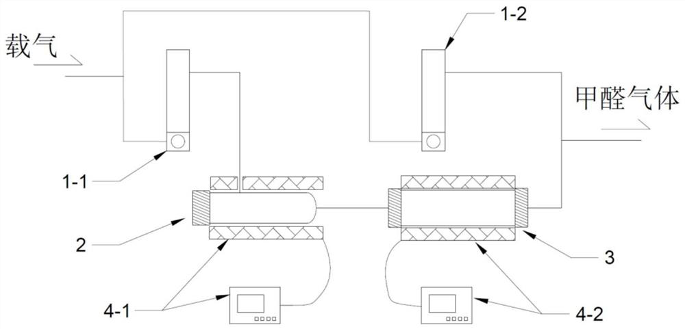
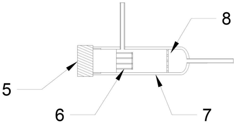
[0004] In order to solve the problems existing in the prior art, the present invention provides a formaldehyde gas generating device based on paraformaldehyde emission and catalytic depolymerization process. The device uses dry and clean air as the gas source and high-purity paraformaldehyde powder as the raw material , by making it into the form of a distributing rod, distributing paraformaldehyde gas at a certain temperature, and depolymerizing the gaseous paraformaldehyde into gaseous single-molecule formaldehyde through a strong acid catalyst section with low water content, so as to meet the test requirements and overcome the existing Problems with unstable formaldehyde gas generating device and inaccurate experimental results in technology

Method used


Image

  • Formaldehyde gas generating device based on paraformaldehyde emission depolymerization
  • Formaldehyde gas generating device based on paraformaldehyde emission depolymerization
  • Formaldehyde gas generating device based on paraformaldehyde emission depolymerization

Examples


Embodiment 1

[0040] use as figure 1 In the device described above, a paraformaldehyde emission rod 13 is added to the emission chamber 2, the operating temperature of the emission chamber 2 is 35°C, the control temperature of the catalytic depolymerization chamber 3 is 220°C, and the actual chamber airflow temperature is about 168°C , using the RM-16 high-precision formaldehyde detector produced by the American interscan company to detect the formaldehyde concentration of the experimental system, and the stability of formaldehyde gas generation is obtained as follows: Figure 5 , the concentration fluctuation is within ±5% of the test standard requirements, meeting the test requirements. At the same time, the depolymerization rate was compared by the weighing method. The weight loss of the solid paraformaldehyde emission rod obtained by the weighing method was 4.3 mg before and after the experiment, and the actual cumulative emission of single-molecule formaldehyde detected by the instrume...


PUM

PropertyMeasurementUnit
thicknessaaaaaaaaaa
lengthaaaaaaaaaa

Abstract

The invention relates to a formaldehyde gas generating device based on paraformaldehyde emission depolymerization. The method comprises a paraformaldehyde emission chamber and a catalytic depolymerization chamber, one end of a small-range gas flow meter is connected with dry clean air, the other end of the small-range gas flow meter is connected with the emission chamber, the emission chamber is wrapped by a PID temperature control heating device, and the outlet of the emission chamber is connected with the catalytic depolymerization chamber. The catalytic depolymerization chamber is wrapped by the PID temperature control heating device, one end of a large-flow gas flow meter is connected with dry clean air, and the other end of the large-flow gas flow meter is connected with an outlet ofthe catalytic depolymerization chamber through a tee joint and is converged and sent to a test system. According to the formaldehyde generating device, dry and clean air is used as an air source, a molten and re-condensed paraformaldehyde emission rod is used as a formaldehyde generating source, glass bead (or silicon carbide) particles coated and dried by phosphoric acid are used as a catalytic depolymerizing agent, and paraformaldehyde gas is depolymerized into monomolecular formaldehyde at 170 DEG C; the stable paraformaldehyde emission rate at a constant temperature is ensured, and the overall gas generation precision and stability of the generation device are improved.

Description

technical field [0001] The invention relates to a formaldehyde gas generating device used for testing experiments of filters and filter materials, in particular to a formaldehyde gas generating device based on paraformaldehyde emission and depolymerization. Background technique [0002] With the improvement of people's health awareness level, people's requirements for indoor air quality are also getting higher and higher. As a major indoor air pollutant, formaldehyde has attracted more and more attention. In order to meet the requirements for air purity in the living environment, air filters are often used to filter and purify formaldehyde in the indoor environment. [0003] Gaseous formaldehyde adsorption test experiment, as a commonly used test method, can effectively evaluate the formaldehyde removal performance of filters and fillers in filter devices. At present, the relevant test standards commonly used in the industry are ASHRAE 145.1 / ASHRAE 145.2 and ISO 10121-1 / IS...

Claims


Application Information

Patent Timeline
Patent Type & Authority Applications(China)
IPC IPC(8): B01J8/02B01J19/02C07C45/51C07C47/04
CPCB01J8/0278B01J8/0285B01J19/02B01J8/001C07C45/513C07C47/04
Inventor 裴晶晶潘奕君代雯华
Owner TIANJIN UNIV
Learn More