
A three-phase thyristor control circuit

A technology of thyristor control and phase thyristor, which is applied in the field of circuits, can solve problems such as large inrush current, electromagnetic interference, and influence on inverter drive, and achieve the effect of protecting devices and reducing inrush current

Active Publication Date: 2022-06-07
KEHUA DATA CO LTD +1
View PDF6 Cites 0 Cited by
  • Summary
  • Abstract
  • Description
  • Claims
  • Application Information

AI Technical Summary

Problems solved by technology

[0003] In the prior art, the transmission of three-phase AC power is often controlled by thyristors, but most of the existing thyristors are controlled by a drive circuit. Through this control method, the switching of the three-phase thyristors is completed at the same time, but due to the three The phases of each phase voltage in the phase electricity are different, and due to the influence of the filter capacitor at the back end of the three-phase thyristor, the voltage difference of each phase thyristor is different at the same time. Therefore, when the three-phase thyristors are turned on at the same time, on the one hand it will A large inrush current will be formed, which will affect the life of the device. On the other hand, it will cause large electromagnetic interference, which will affect the drive of the inverter, etc.

Method used


Image

  • A three-phase thyristor control circuit
  • A three-phase thyristor control circuit

Examples


Embodiment 1

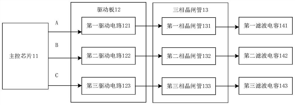
[0042] Embodiments of the present application provide a three-phase thyristor control circuit, such as Figure 1 As shown, the three-phase thyristor control circuit comprising: based on the first master signal A drive first phase thyristor 131 first drive circuit 121; Further, based on the second master signal B to drive the second phase thyristor 132 of the second drive circuit 122; Further, based on the third master signal C drive third phase thyristor 133 third drive circuit 123; And, respectively, the first drive circuit 121, the second drive circuit 122 and the third drive circuit 123 connected to the main control chip 11; The above-described main control chip 11 is configured to transmit the corresponding master signal to the corresponding driving circuit of the target thyristor, wherein the target thyristor is the first phase thyristor 131, the second phase thyristor 132, the third phase thyristor 133, the difference between the input voltage instantaneous value and the outp...

Embodiment 2

[0059] Embodiments of the present application provide a three-phase thyristor control circuit, such as Figure 1As shown, the three-phase thyristor control circuit comprising: based on the first master signal A drive first phase thyristor 131 first drive circuit 121; Further, based on the second master signal B to drive the second phase thyristor 132 of the second drive circuit 122; Further, based on the third master signal C drive third phase thyristor 133 third drive circuit 123; And, respectively, the first drive circuit 121, the second drive circuit 122 and the third drive circuit 123 connected to the main control chip 11; Wherein, the above-described main control chip 11 is configured to: the first phase thyristor 131, the second phase thyristor 132, the third phase thyristor 133 when crossing the zero point to the corresponding thyristor corresponding to the corresponding driver circuit to send the corresponding master signal.

[0060] Since the three-phase thyristor 13 corre...


PUM


Abstract

The present application provides a three-phase thyristor control circuit, which belongs to the field of circuit technology, wherein the three-phase thyristor control circuit includes: a first drive circuit for driving the first-phase thyristor based on the first main control signal; a second drive circuit for driving the thyristors of the second phase; a third drive circuit for driving the thyristors of the third phase based on the third main control signal; and a main control circuit respectively connected to the first drive circuit, the second drive circuit and the third drive circuit chip; the main control chip is configured to: send a corresponding main control signal to the drive circuit corresponding to the target thyristor, wherein the target thyristor is the first phase thyristor, the second phase thyristor, and the third phase thyristor, the input voltage instantaneous value and Thyristors for which the difference between the instantaneous values ​​of the output voltage is less than the threshold. The three-phase thyristor control circuit provided in the present application can realize the sequential opening of each phase thyristor in the three-phase thyristor, and reduces the surge current formed when the three-phase thyristor is turned on.

Description

Technical field [0001] The present application belongs to the field of circuit technology, in particular involving a three-phase thyristor control circuit. Background [0002] Thyristor is the abbreviation of the transistor flow tube, also known as the thyristor rectifier, formerly referred to as silicon Controlled Rectifier (SCR), is a PNPN four-layer semiconductor structure, with the characteristics of silicon rectifier devices, can work under high voltage, high current conditions, and its working process can be controlled, is widely used in controllable rectifier, AC voltage regulation, contactless electronic switch, inverter and frequency conversion and other electronic circuits. [0003] In the prior art, the transmission of three-phase alternating current is often controlled by the thyristor, but the existing thyristor is mostly controlled by a drive circuit, through this control method, the switch of the three-phase electric thyristor is completed at the same time, but due...

Claims


Application Information

Patent Timeline
Patent Type & Authority Patents(China)
IPC IPC(8): H02M1/06H02M1/36
CPCH02M1/06H02M1/36H02M1/0058Y02B70/10
Inventor 钟小帆周超伟吴庆彬苏景山陈志清
Owner KEHUA DATA CO LTD
Learn More