
Oil-gas separation device for internal combustion engine

A separation device, oil and gas separator technology, applied in mechanical equipment, engine components, machines/engines, etc., can solve the problems of engine carbon deposition, air pollution, unqualified, etc. The effect of oil recovery

Pending Publication Date: 2020-12-29
江苏宝时达动力科技有限公司
View PDF0 Cites 0 Cited by
  • Summary
  • Abstract
  • Description
  • Claims
  • Application Information

AI Technical Summary

Problems solved by technology

[0002] In modern society, cars are widely used as an important means of transportation. When the engine of a car burns and does work, it will inevitably emit exhaust gas. The exhaust gas will contain organic oil vapor and water vapor from the combustion chamber. , if it is not treated, the oil vapor and water vapor will be discharged directly, which will cause the phenomenon of burning oil, and also cause carbon deposits inside the engine, and also pollute the air, so it is necessary to design an oil-gas separation equipment that can Recycling the engine oil, so as to avoid the purpose of burning engine oil and engine carbon deposition, and also avoiding the defect of unqualified automobile exhaust

Method used


Image

  • Oil-gas separation device for internal combustion engine
  • Oil-gas separation device for internal combustion engine
  • Oil-gas separation device for internal combustion engine

Examples


Embodiment Construction

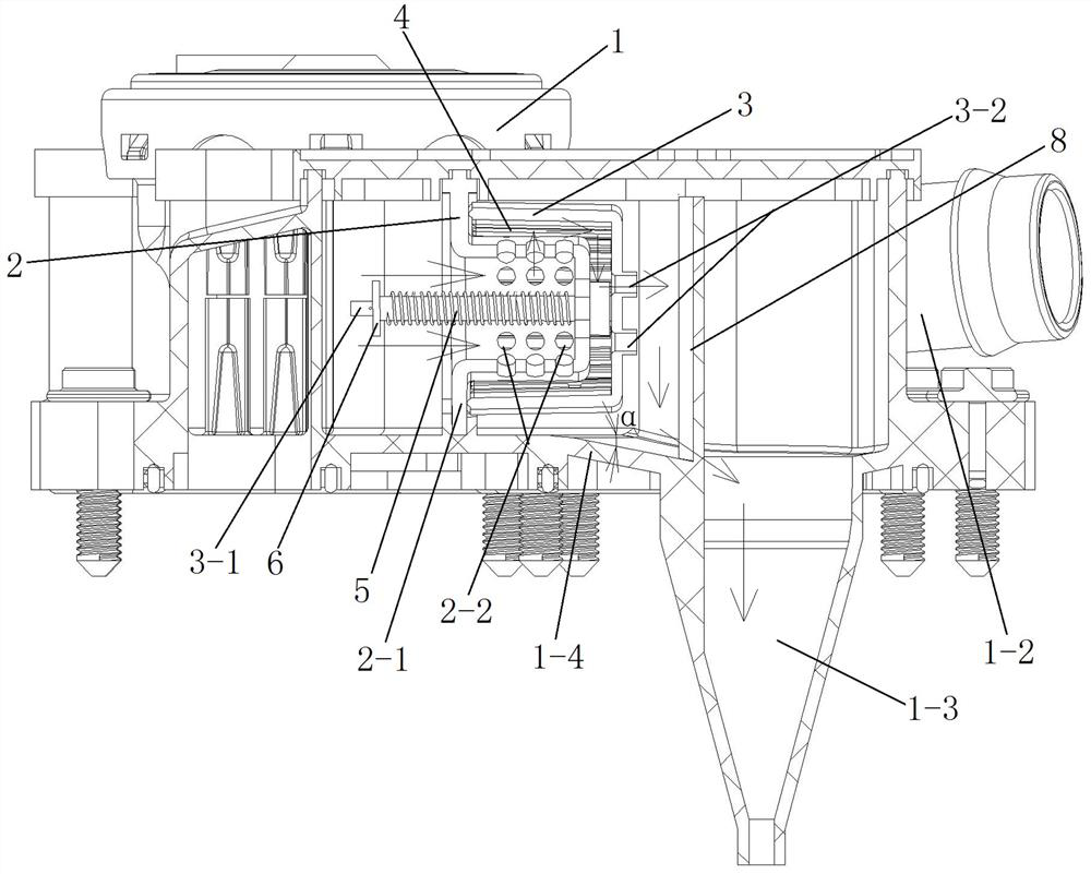
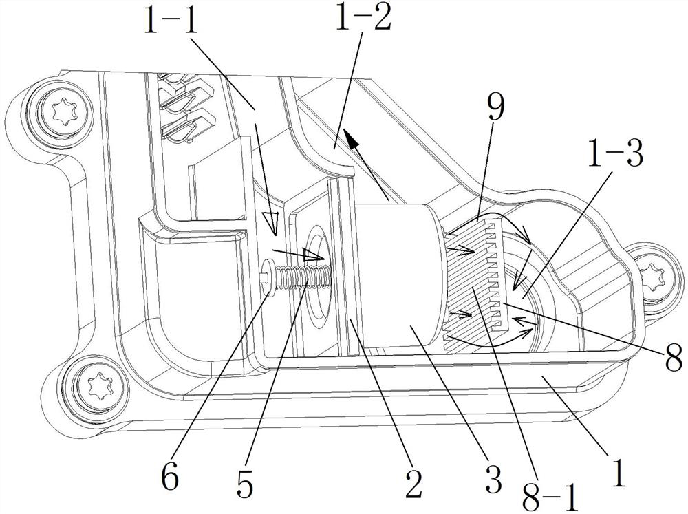
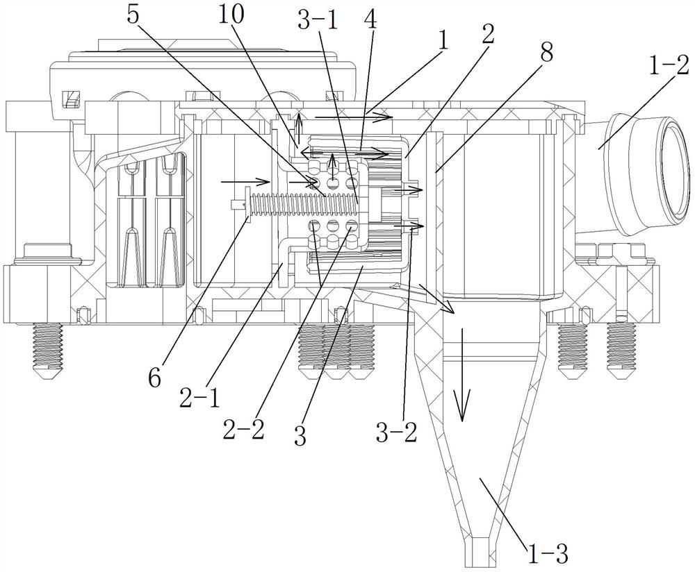
[0026] Refer to attached Figure 1-8 , an oil-gas separation device for an internal combustion engine, having a mounting base 1, an air intake passage 1-1 and an air outlet passage 1-2 are respectively arranged in the installation base 1, and the air intake passage 1-1 and the air outlet passage 1 An oil-air separator is installed at the intersection of -2, and an oil outlet channel 1-3 is also provided at the rear end of the oil-air separator for recovering the separated engine oil. A closed cover plate is installed above the installation base for Cover the air inlet passage 1-1, the air outlet passage 1-2, the oil-gas separator and the oil outlet passage 1-3.

[0027] The oil-gas separator has a cylindrical inner sleeve 2, and the outer wall of the inner sleeve 2 is provided with a matching outer sleeve 3; wherein the inner sleeve 2 has an outwardly turned flange 2-1, Corresponding slots are provided on the installation base 1, and the inner sleeve 2 can be clamped and inst...


PUM


Abstract

The invention discloses an oil-gas separation device for an internal combustion engine, and relates to oil-gas separation equipment for a gasoline engine or a diesel engine. The oil-gas separation device for the internal combustion engine is provided with a mounting base, a gas inlet channel and a gas outlet channel are arranged in the mounting base, an oil-gas separator is mounted at the junctionof the gas inlet channel and the gas outlet channel, and an oil outlet channel is further arranged at the rear end of the oil-gas separator. The oil-gas separator is provided with a cylindrical innersleeve, and the outer wall of the inner sleeve is sleeved with a matched outer sleeve; the inner sleeve is provided with a flanging turned outwards, a corresponding clamping groove is formed in the mounting base, the inner sleeve can be clamped and mounted in the mounting base through the flanging, and a plurality of first through holes are formed in the periphery of the inner sleeve; an axial hole is formed in the circle center of the inner sleeve, and an extending section turned outwards is further arranged at the axial hole; and a pin is arranged at the circle center of the bottom of the outer sleeve, and the outer sleeve movably sleeves the outer part of the inner sleeve by inserting a pin into the axial hole in a penetrating mode.

Description

technical field [0001] The invention relates to an oil-gas separation device for an internal combustion engine, which relates to an oil-gas separation device for a gasoline engine or a diesel engine. Background technique [0002] In modern society, cars have been widely used as an important means of transportation. When the engine of a car burns and does work, it will inevitably emit exhaust gas. The exhaust gas will contain organic oil vapor and water vapor from the combustion chamber. , if it is not treated, the oil vapor and water vapor will be discharged directly, which will cause the phenomenon of burning oil, and also cause carbon deposits inside the engine, and also pollute the air, so it is necessary to design an oil-gas separation device that can The engine oil is recycled, so as to avoid burning engine oil and engine carbon deposits, and also avoid the defect of unqualified automobile exhaust. Contents of the invention [0003] In view of this, the present inven...

Claims


Application Information

Patent Timeline
Patent Type & Authority Applications(China)
IPC IPC(8): F01M11/08
CPCF01M11/08
Inventor 汤懋来李国金杨正凯常江鹏常宝国杨柳园
Owner 江苏宝时达动力科技有限公司
Learn More