
Soil sampling device suitable for vertical shaft and sampling method

A vertical well and soil sample technology, which is applied to earth drilling, wellbore/well components, buildings, etc., can solve the problems of large soil disturbance and damage, complicated operation process, and low sampling success rate, so as to reduce potential safety hazards, The effect of improving sampling efficiency and reducing labor intensity

Pending Publication Date: 2020-12-29
CHINA HYDROELECTRIC ENGINEERING CONSULTING GROUP CHENGDU RESEARCH HYDROELECTRIC INVESTIGATION DESIGN AND INSTITUTE
View PDF6 Cites 0 Cited by
  • Summary
  • Abstract
  • Description
  • Claims
  • Application Information

AI Technical Summary

Problems solved by technology

[0005] Aiming at the technical problems of the above-mentioned undisturbed soil sampling device for vertical shafts with complex operation process, low sampling efficiency, large disturbance and damage to the soil and low sampling success rate, the present invention provides a simple structure, small disturbance to the soil, and a high degree of automation suitable for vertical shafts. Soil sampling device and sampling method

Method used


Image

  • Soil sampling device suitable for vertical shaft and sampling method

Examples


Embodiment 1

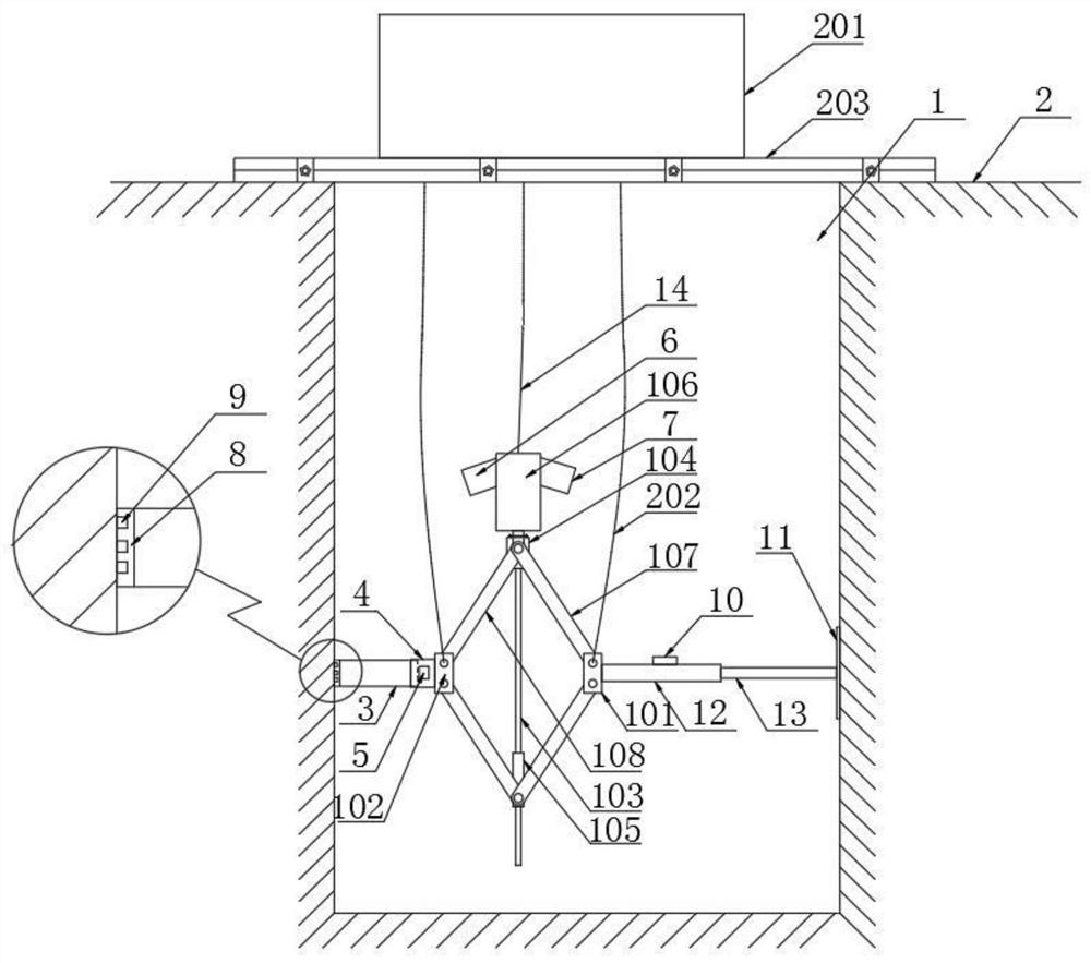
[0033] refer to figure 1, a kind of soil sampling device applicable to vertical shafts of the present invention comprises a sampling mechanism arranged in the vertical shaft and a lifting mechanism arranged on the top of the vertical shaft for driving the sampling mechanism to lift in the vertical direction; the sampling mechanism includes horizontally arranged For the support rod in the shaft, one end of the support rod is connected to the inner wall of the shaft 1, and the other end is connected to the inner wall of the shaft through the power mechanism and the hollow sampling tube 3 in turn; The support 101 and the second support 102, a screw 103 is vertically arranged between the first support 101 and the second support 102; the top of the screw is provided with a connecting seat 104 fixedly connected to the screw, and the end of the connecting seat is connected Motor 106; The threaded sleeve 105 that is provided with the screw thread matching of screw rod on the screw rod...

Embodiment 2

[0043] Sampling method adopts a kind of soil sampling device applicable to shafts described in embodiment one, comprising the following steps:

[0044] S1. According to the diameter of the shaft, the length of the support rod is adjusted by rotating the support rod, so that the overall length of the sampling mechanism is slightly smaller than the diameter of the shaft;

[0045] S2. Set up the lifting mechanism on the top of the shaft, and lower the sampling mechanism to the predetermined sampling position through the lifting mechanism;

[0046] S3, observe the levelness of the sampling mechanism by a spirit level, adjust different wire ropes to keep the sampling mechanism in a horizontal state; then observe the contact situation between the sampling pipe and the backing plate and the inner wall of the shaft through the first camera and the second camera;

[0047] S4. Drive the sampling pipe through the power mechanism to steadily and slowly press the soil body in the shaft unt...


PUM


Abstract

The invention discloses a soil sampling device suitable for a vertical shaft and a sampling method. The soil sampling device comprises a sampling mechanism arranged in the vertical shaft and a liftingmechanism arranged at the top of the vertical shaft and used for driving the sampling mechanism to ascend and descend in the vertical direction. The sampling mechanism comprises a supporting rod horizontally arranged in the vertical shaft, one end of the supporting rod is connected with the inner wall of the vertical shaft, and the other end of the supporting rod is connected with the inner wallof the vertical shaft sequentially through a power mechanism and a hollow sampling pipe. According to the power mechanism of the soil sampling device, the sampling pipe is slowly inserted into a soilbody in the vertical shaft by adopting the principle of a mechanical jack, the soil body is prevented from being disturbed and destroyed by the sampling pipe, the integrity of undisturbed soil is ensured as much as possible, subsequent tests are facilitated, and test errors are reduced; and meanwhile, traditional manual operation is replaced, the labor intensity is reduced, the sampling efficiencyis improved, potential safety hazards are reduced, the device is simple and convenient to disassemble and assemble, and time and labor are saved.

Description

technical field [0001] The invention relates to the technical field of geotechnical exploration engineering, in particular to a soil sampling device and sampling method suitable for shafts. Background technique [0002] With the acceleration of large-scale engineering construction in construction, municipal, transportation and other industries, the level of survey and design has been developed rapidly, and the requirements for taking soil samples have also increased. At present, for sampling soil, it is often required to keep it in its original state. However, soil is a variety of sediments produced by complex natural environments such as rock weathering, denudation, transportation, and deposition. It is a three-phase system composed of solid matter, water, and gas. The soil structure is relatively loose. During operation, sample packaging, storage, and transportation, it is easy to disturb and destroy its original structural system, resulting in difficulty in sampling undi...

Claims


Application Information

Patent Timeline
Patent Type & Authority Applications(China)
IPC IPC(8): E21B49/02E21B49/06E21B47/002
CPCE21B49/02E21B49/06
Inventor 李青春胡亚东马金根王能峰
Owner CHINA HYDROELECTRIC ENGINEERING CONSULTING GROUP CHENGDU RESEARCH HYDROELECTRIC INVESTIGATION DESIGN AND INSTITUTE
Learn More