
Automatic rubber feeding machine

An automatic feeding and rubber technology, applied in the direction of conveyor objects, loading/unloading, cleaning devices, etc., can solve the problems of accumulated rubber sticky dirt, difficult to cut, rubber bottom adhesion, etc., to reduce slippage and facilitate post-processing effects

Inactive Publication Date: 2020-12-29
贺子豪
View PDF0 Cites 0 Cited by
  • Summary
  • Abstract
  • Description
  • Claims
  • Application Information

AI Technical Summary

Problems solved by technology

[0004] The main purpose of the present invention is to overcome the deficiencies of the prior art and provide an automatic rubber feeder to solve the problem of rubber being transported by the conveyor belt. In high-temperature environments, the rubber has a high viscosity and will stick to the surface of the conveyor belt, making it difficult to cut off completely. , the surface of the conveyor belt will accumulate rubber sticky dirt, which is difficult to clean, and the bottom of the rubber will also stick, and the rubber strip after cutting is prone to deformation.

Method used


Image

  • Automatic rubber feeding machine
  • Automatic rubber feeding machine
  • Automatic rubber feeding machine

Examples


Embodiment 1

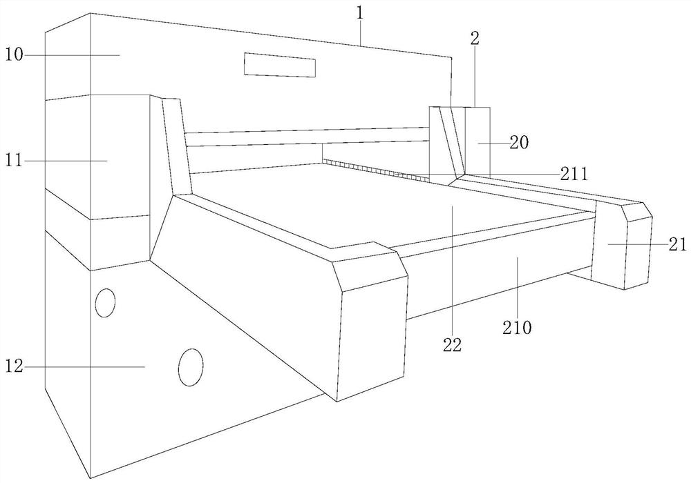
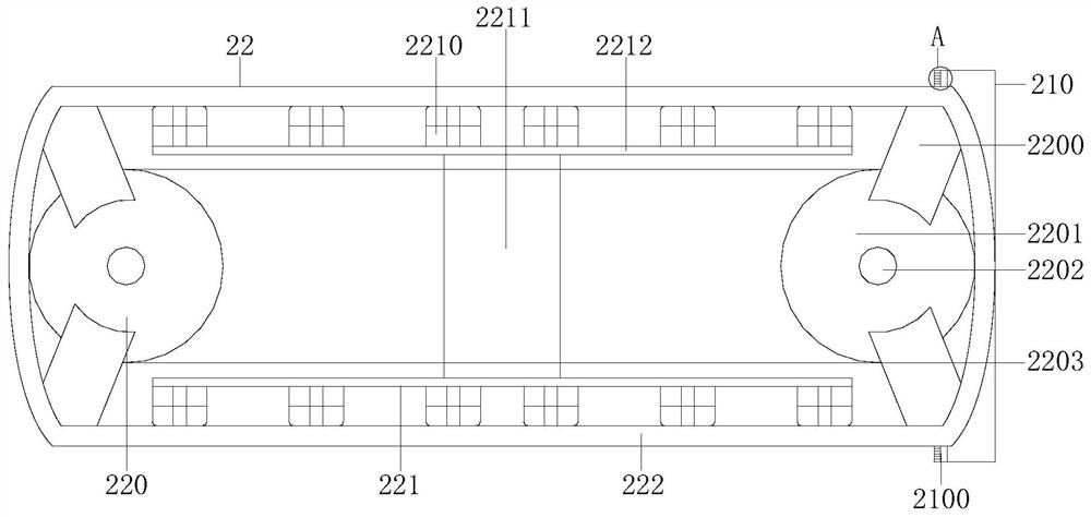
[0024] Example 1 see Figure 1-3 , the present invention provides a technical solution for a rubber automatic feeding machine: its structure includes a feeding frame 1 and a conveying frame 2, the feeding frame 1 is installed and connected to the rear end of the conveying frame 2, and the feeding machine The frame 1 is composed of an upper frame 10, a middle frame 11, and a bottom frame 12. The upper frame 10 is connected to the upper end of the middle frame 11, and the upper end of the middle frame 11 is locked with the bottom frame 12. The conveyor frame 2 includes a side frame 20 , conveying rack 21, conveying structure 22, described side mounting frame 20 is installed and connected with the rear end of conveying rack 21, the left and right ends of described conveying structure 22 are embedded in conveying rack 21, and the front end of described conveying rack 21 is installed There is a pre-conveying rack 210, and a side-mounted air conditioner 211 is installed at the rear ...

Embodiment 2

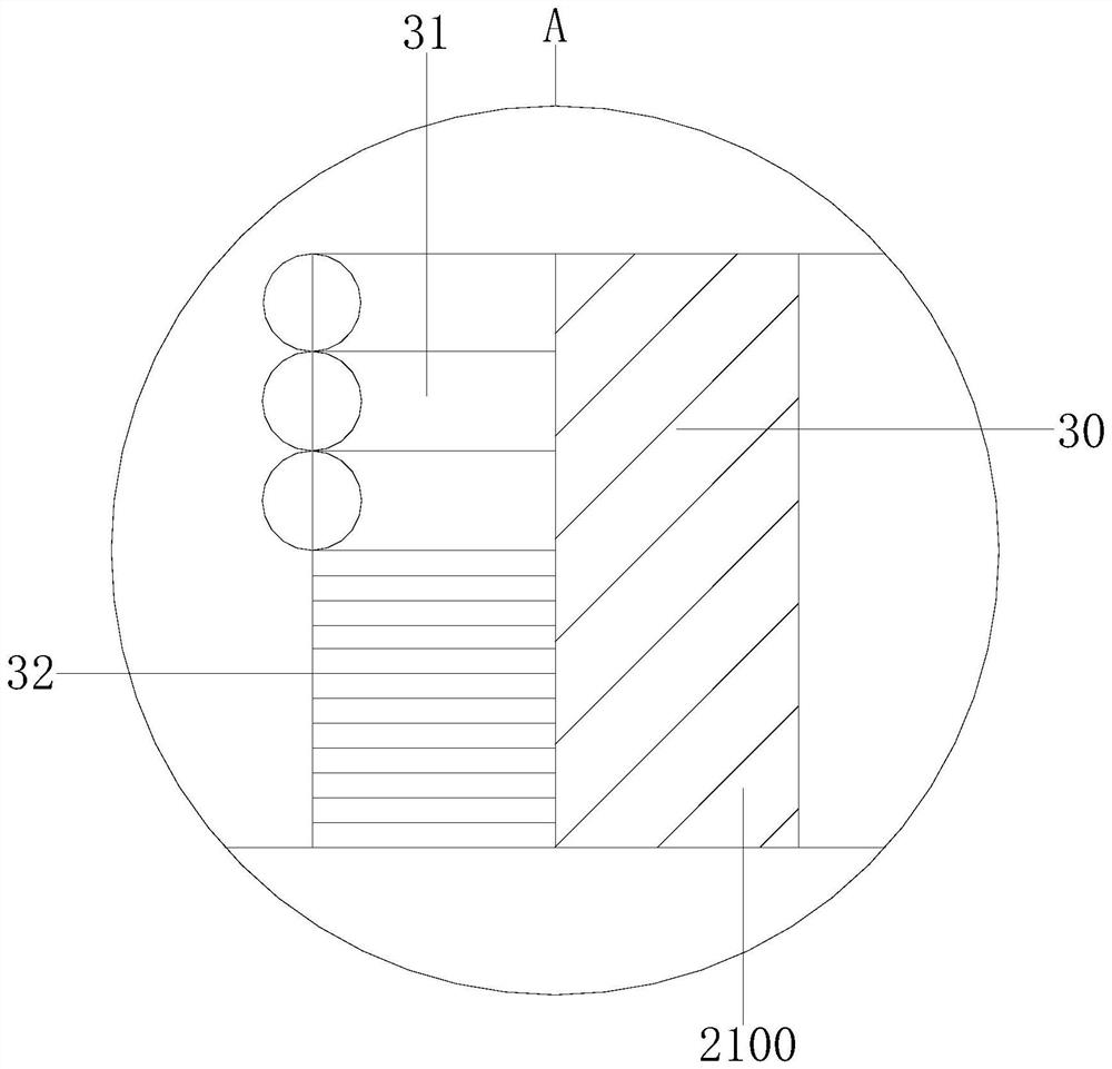
[0026] Example 2 see Figure 4-5 , the present invention provides a technical solution for an automatic rubber feeder: the convex structure 2210 includes a push rod 40, a main frame 41, and a horizontal bracket 42, and the main frame 41 is installed and connected to the push rod 40 and the horizontal bracket 42. The push rod 40 is connected to the middle track of the horizontal support 42. The left and right ends of the push rod 40 are arc-shaped structures, which minimize the wear and tear on the conveying structure 22 when pushing up. The conveying belt 222 includes a bottom belt 2220 , the middle belt 2221, the upper belt 2222, the upper and lower sides of the middle belt 2221 are glued to the bottom belt 2220 and the upper belt 2222, the middle part of the middle belt 2221 is provided with a grain bin 50, and the upper part of the upper belt 2222 is provided with a rubber The convex strip 51, the rubber convex strip 51 reduces the slipping of the rubber during transportati...


PUM


Abstract

The invention discloses an automatic rubber feeding machine. The machine structurally comprises a feeding machine frame and a conveying machine frame, wherein the feeding machine frame is connected with the conveying machine frame, the feeding machine frame is composed of an upper frame, a middle frame and a bottom frame, the upper frame is connected with the middle frame, the middle frame is locked with the bottom frame, the conveying machine frame comprises a side mounting frame, a conveying mounting frame and a conveying structure, the side mounting frame is connected with the conveying mounting frame, the conveying structure is embedded in the conveying mounting frame, the conveying mounting frame is provided with a conveying front mounting frame and a side-mounted cold air machine, the conveying front mounting frame and the side-mounted cold air machine are vertically distributed, the conveying structure comprises a rotating wheel, a work frame and a conveying belt, and the rotating wheel abuts against the work frame. According to the machine, main cold air machines and the side-mounted cold air machine convey cold air to reduce a temperature, convex structures drive a conveying belt to shake, an effect that when rubber adheres to a surface layer and the bottom of the conveying belt, the conveying belt is enabled to do shaking actions to shake off a small amount of adhering rubber crushed aggregates is achieved, and rubber convex strips play a role in reducing slipping during rubber conveying, fixing the rubber and facilitating later processing.

Description

technical field [0001] The invention relates to the technical field of rubber processing, in particular to an automatic rubber feeding machine. Background technique [0002] Rubber is a highly elastic polymer material with reversible deformation. It is full of elasticity and can produce large deformation under the action of external force. It can return to its original shape after the external force is removed. Rubber is made by coagulating and drying the latex flowing out of the rubber tree. [0003] In the prior art, the rubber is transported by the conveyor belt. Under the high temperature environment, the rubber has a high viscosity and will stick to the surface of the conveyor belt, which is difficult to cut completely. The surface of the conveyor belt will accumulate rubber sticky dirt, which is difficult to clean. The rubber bottom will also stick. The rubber strip is prone to deformation. Contents of the invention [0004] The main purpose of the present invention...

Claims


Application Information

Patent Timeline
Patent Type & Authority Applications(China)
IPC IPC(8): B65G45/10B65G69/20
CPCB65G45/105B65G69/20
Inventor 贺子豪
Owner 贺子豪
Learn More