
Heating, temperature detection and optical detection devices and methods for micro-fluidic chip

A technology of a temperature detection device and a microfluidic chip, which is applied to the heating of a microfluidic chip, a microfluidic chip system, a temperature detection and an optical detection device, and can solve problems such as chip structure damage and cross-contamination of the microfluidic chip. , to facilitate rapid control and improve heat transfer efficiency

Pending Publication Date: 2020-12-29
深圳市和来生物技术有限公司
View PDF11 Cites 2 Cited by
  • Summary
  • Abstract
  • Description
  • Claims
  • Application Information

AI Technical Summary

Problems solved by technology

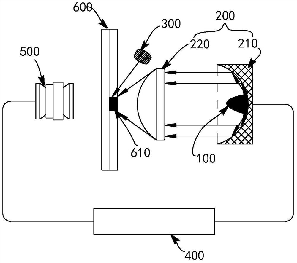
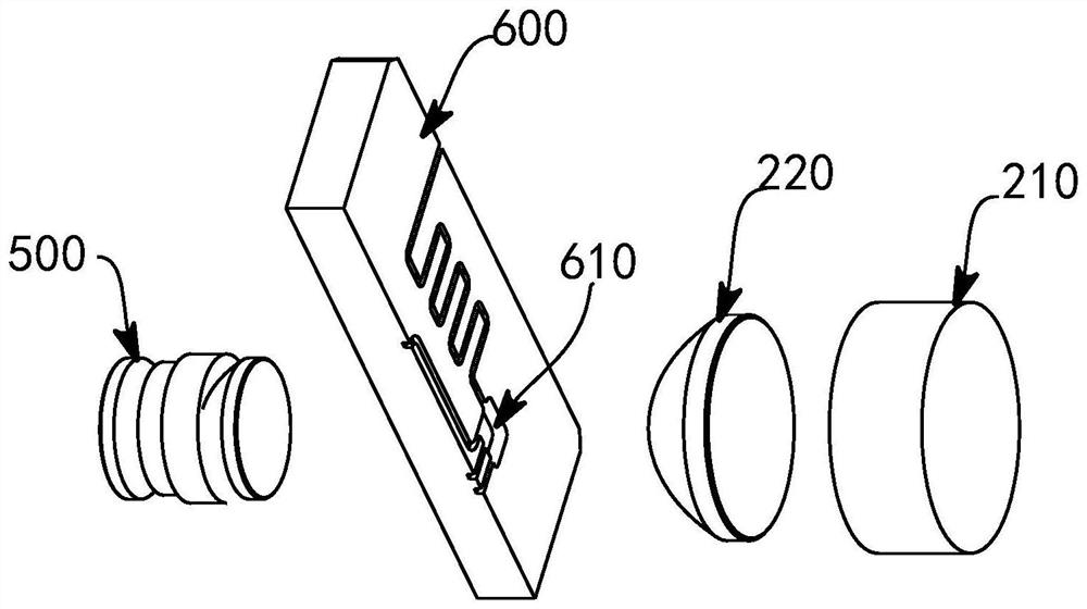
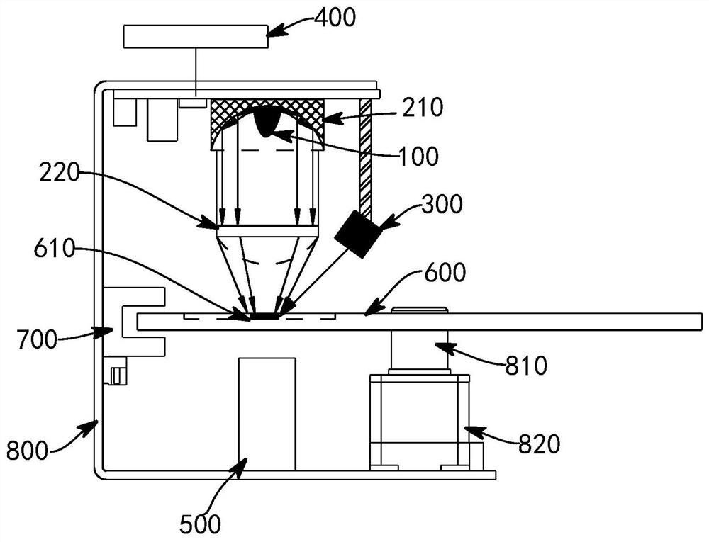
[0004] Specifically, this application solves the problems of cross-contamination and chip structure damage existing in microfluidic chips during heating by adopting the method of separating the heating element from the heating area.

Method used


Image

  • Heating, temperature detection and optical detection devices and methods for micro-fluidic chip
  • Heating, temperature detection and optical detection devices and methods for micro-fluidic chip
  • Heating, temperature detection and optical detection devices and methods for micro-fluidic chip

Examples


Embodiment Construction

[0070] The present invention will be further described in detail below in conjunction with the accompanying drawings, so that those skilled in the art can implement it with reference to the description.

[0071] The term "plurality" in the embodiments of the present application means at least two, such as two, three, etc., unless otherwise specifically defined. In addition, the orientations or positional relationships indicated by "upper", "lower", "top", "bottom", "inner", "outer", etc. are based on the orientation or positional relationships shown in the drawings, and are only for the convenience of describing the present invention. The invention and simplified description do not indicate or imply that the referred device or device must have a specific orientation, be constructed and operate in a specific orientation, and thus should not be construed as limiting the present invention. Furthermore, the terms "comprising" and "provided with", as well as any variations thereof,...


PUM


Abstract

The invention provides a heating device of a micro-fluidic chip. The heating device comprises a heating body which is separated for a predetermined distance from a heating area of themicro-fluidic chip and a focusing device which is used for focusing heat emitted by the heating body to the heating area. On the basis, the invention further provides a heating, temperature detection and optical detection device and method for the micro-fluidic chip and a micro-fluidic chip system. According to the invention, the problems of cross contamination and chip structure damage of the micro-fluidic chip during heating are solved.

Description

technical field [0001] The invention relates to the technical field of microfluidic chips. More specifically, the present invention relates to a microfluidic chip heating, temperature detection and optical detection device and method and a microfluidic chip system. Background technique [0002] Because the reaction process of in vitro diagnostic reagents usually requires relatively high temperature, and its reactivity is the strongest in a suitable temperature range, so the quality of temperature control directly affects the detection results. The temperature control scheme used by traditional inspection equipment in the reagent reaction process is mainly a constant temperature bag. This solution mainly adopts resistance heating, semiconductor heating, etc., and has the characteristics or shortcomings such as large and bulky, high power consumption, high cost, long time required to reach a constant temperature range, and high failure rate. There are also some devices that ...

Claims


Application Information

Patent Timeline
IPC IPC(8): B01L7/00G01J5/12G01K7/22G01N21/17G01N35/00
CPCB01L7/00G01N35/00G01N21/17G01J5/12G01K7/22B01L2300/1861
Inventor 周昭瑞梁品洪刘成
Owner 深圳市和来生物技术有限公司
Learn More