Electric mechanical lifting structure with high safety

A lifting structure and safety technology, applied in the field of electromechanical lifting structures, can solve problems such as hidden dangers, loosening safety of electromechanical lifting structures, etc., and achieve the effect of preventing potential safety hazards.

Active Publication Date: 2020-12-25
上海领升自动化系统有限公司
View PDF7 Cites 0 Cited by
  • Summary
  • Abstract
  • Description
  • Claims
  • Application Information

AI Technical Summary

Problems solved by technology

[0003] When the electromechanical lifting structure lifts the object during use, due to the heavy weight of some objects, at the same time, when the electromechanical lifting structure lifts the object to the designated position, it usually needs to stay for a period of time for corresponding operations Work, so that the object is easy to loosen on the electromechanical lifting structure and form a certain safety hazard

Method used


Image

  • Electric mechanical lifting structure with high safety
  • Electric mechanical lifting structure with high safety
  • Electric mechanical lifting structure with high safety

Examples


Embodiment 1

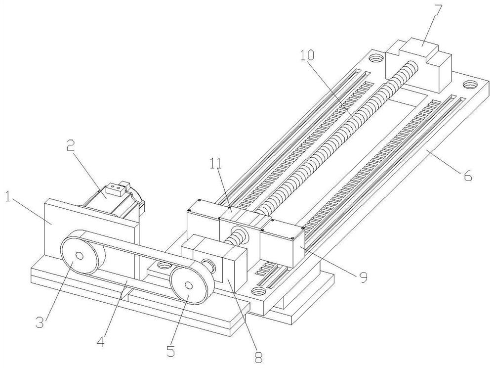
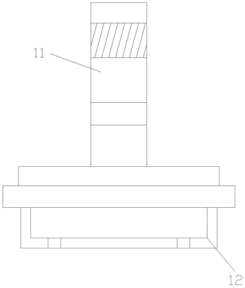
[0026] see figure 1 and figure 2 , the present invention provides a highly safe electromechanical lifting structure through improvement, including a fixed frame 1, a motor 2 and a T-shaped slide plate 11, the fixed frame 1 is installed on the rear end surface of the bottom plate 6, and the motor 2 is locked on the fixed frame 1 On the left end of the front end, the output shaft at the rear end of the motor 2 passes through the front end of the fixed frame 1 and is connected to the inner ring of the driving wheel 3. The right end face of the moving wheel 5 and the front and rear ends of the top end of the bottom plate 6 are respectively welded with a first side plate 7 and a second side plate 8, and the front and rear opposite middle parts of the first side plate 7 and the second side plate 8 rotate with the outer front and rear ends of the screw rod 10. Connection, the screw rod 10 penetrates through the middle of the rear end surface of the second side plate 8 and is fasten...

Embodiment 2

[0031] The present invention provides a high-safety electromechanical lifting structure through improvement. There are mounting holes on the top surface of the bottom plate 6, and four mounting holes are distributed on the four ends of the top surface of the bottom plate 6, so that the bottom plate 6 can be easily installed through the mounting holes. At a designated position, the mounting frame 12 is a U-shaped structure, and four ends of the bottom surface of the mounting frame 12 are provided with connection holes, which allow the mounting frame 12 to be stably connected to external objects.

[0032] The present invention provides an electromechanical lifting structure with high safety through improvement, and its working principle is as follows;

[0033] First, firstly, the whole device is fixedly installed on the designated position through the mounting hole on the top of the base plate 6, and at the same time, the external object is fixedly connected to the mounting frame...


PUM


Abstract

The invention discloses an electric mechanical lifting structure with high safety. The electric mechanical lifting structure with high safety comprises a fixing frame, a motor, a bottom plate, a screwrod, a T-shaped sliding plate, a mounting frame, a guide block and an auxiliary fixing mechanism. According to the invention, the auxiliary fixing mechanism is arranged on the outer side of the T-shaped sliding plate, and an electromagnet is electrified to apply an attraction force to an L-shaped plate, at the moment, the L-shaped plate moves leftwards to enable a rotating plate to rotate anticlockwise; during the anticlockwise rotating process of the rotating plate, a ratchet wheel and a disc is pulled to rotate through an L-shaped pulling plate; since the outer surface of the disc is an arcwavy shape, the protruding part on the outer surface of the disc pushes a cross-shaped clamping rod to move downwards in the rotating process of the disc, so that the cross-shaped clamping rod entersthe inner side of a clamping groove formed in the top end face of the bottom plate for fixing, and meanwhile, the positions of a shell and the T-shaped sliding plate are fixed; and therefore, the beneficial effects of further reinforcing the electric mechanical lifting structure and preventing potential safety hazards caused by looseness are achieved.

Description

technical field [0001] The invention relates to the field of lifting structures, in particular to an electromechanical lifting structure with high safety. Background technique [0002] The electromechanical lifting structure is a mechanical device that uses electric energy as power to lift or load and unload. With the continuous development of society, the electromechanical lifting structure has been widely used, especially in the automobile manufacturing industry. In the automobile manufacturing industry, The opening or closing of the tailgate of a car usually adopts an electromechanical lifting structure, or in other manufacturing industries, the electromechanical lifting structure has also been widely used. [0003] When the electromechanical lifting structure lifts objects during use, due to the heavy weight of some objects, at the same time, when the electromechanical lifting structure lifts the objects to the designated position, it usually needs to stay for a period o...

Claims


Application Information

Patent Timeline
Patent Type & Authority Applications(China)
IPC IPC(8): B66F11/00F16H37/12
CPCB66F11/00F16H37/124
Inventor 丘慰兴
Owner 上海领升自动化系统有限公司
Why Eureka
Try Eureka