Thread splitting and winding device for textile

A winding device and textile technology, applied in the direction of transportation and packaging, delivery of filamentous materials, thin material processing, etc., can solve problems such as the inability to adjust the tightness of textile threads and broken threads of textile threads, so as to ensure stability and guarantee Cleanliness, the effect of meeting the needs of winding

Inactive Publication Date: 2020-12-25
尹冬岩
View PDF9 Cites 3 Cited by
  • Summary
  • Abstract
  • Description
  • Claims
  • Application Information

AI Technical Summary

Problems solved by technology

A textile winding device in the above-mentioned patent has the following disadvantages: the tightness of the textile thread cannot be adjusted during winding, which may easily cause the textile thread to break during the winding process.

Method used


Image

  • Thread splitting and winding device for textile
  • Thread splitting and winding device for textile
  • Thread splitting and winding device for textile

Examples


Embodiment 1

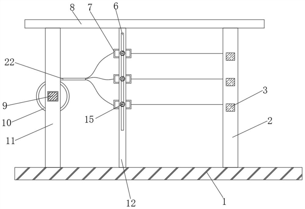
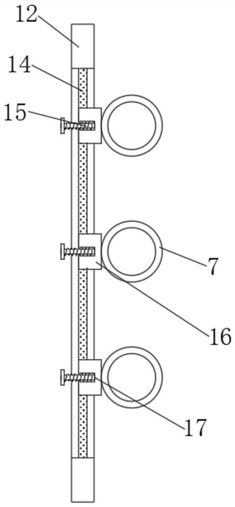
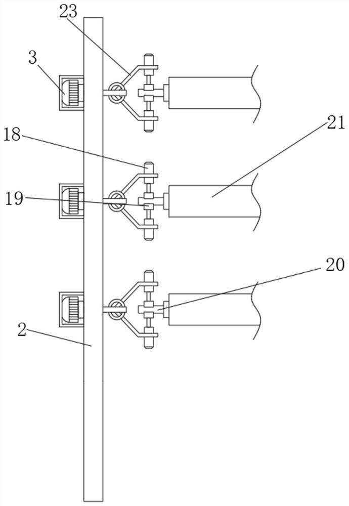
[0026] refer to Figure 1-4 , a textile branch winding device, comprising a bottom plate 1, the top outer wall of the bottom plate 1 is respectively connected with a first support plate 2 and a second support plate 11 by bolts, and the tops of the first support plate 2 and the second support plate 11 are The outer wall is connected with the top plate 8 by bolts, the one side outer wall of the second support plate 11 is connected with the third motor 9 by bolts, and the outer wall of one end of the output shaft of the third motor 9 is fixedly connected with the pay-off roller 10, and the circumference of the pay-off roller 10 The outer wall is wound with a textile thread 22, and the outer wall on one side of the first support plate 2 is connected with the first motor 3 equidistantly distributed by bolts, and the outer wall of the output shaft circumference of the first motor 3 is fixedly connected with a mounting plate 23, and the mounting plate 23- The side outer wall is plugg...

Embodiment 2

[0030] refer to Figure 5 , a textile thread winding device. Compared with Embodiment 1, the top outer wall of the top plate 8 is connected with a protective shell by bolts, and the top inner wall of the protective shell is connected with a second motor 4 by bolts. The second motor The outer wall of one end of the output shaft of 4 is fixedly connected with a brush roller 5, and the peripheral outer wall of the brush roller 5 is in contact with the textile thread 22, and the top outer wall of the bottom plate 1 is connected with a bearing seat 13 by bolts, and the brush roller 5 and the bearing seat The bottom inner wall of 13 forms a rotational connection.

[0031] Working principle: when the take-up roller 21 is winding the textile thread, the second motor 4 can be started, and the second motor 4 drives the brush roller 5 to rotate together, and the textile thread can be cleaned of dust through the rotation of the brush roller 5 , to ensure the cleanliness of the textile th...


PUM


Abstract

The invention discloses a thread splitting and winding device for textile. The thread splitting and winding device comprises a bottom plate, the outer wall of the top of the bottom plate is connectedwith a first supporting plate and a second supporting plate through bolts, and a top plate is arranged on the outer walls of the tops of the first supporting plate and the second supporting plate. A third motor is arranged on the outer wall of one side of the second supporting plate, and the outer wall of one end of an output shaft of the third motor is fixedly connected with a pay-off roller. Textile threads are wound on the outer wall of the circumference of the pay-off roller. A thread guide barrel on the outer wall of one side of a fixing plate can guide and wind the split textile threads.Meanwhile, the guide barrel can slide a sliding block before guiding the textile threads, so that the position of the thread guide barrel is adjusted, and the tightness of the textile threads is adjusted. After the sliding block slides, people can make a fixing screw rod penetrate through a through groove and insert the fixing screw rod into a threaded groove formed in the outer wall of one sideof the sliding block, so that the sliding block can be limited and fixed, and the stability of the sliding block and the guide barrel is guaranteed.

Description

technical field [0001] The invention relates to the technical field of textile production, in particular to a textile thread dividing and winding device. Background technique [0002] The original meaning of textile is taken from the general term of spinning and weaving, but with the continuous development and improvement of the textile knowledge system and subject system, especially after the emergence of non-woven textile materials and three-dimensional composite weaving technologies, the current textile is not only a traditional Hand spinning and weaving also include garment, industrial and decorative textiles produced by non-woven technology, modern three-dimensional weaving technology, and modern electrostatic nano-netting technology. [0003] After searching, the Chinese patent application number is CN208732337U, which discloses a textile winding device, including a bottom plate, a vertical plate and an SPT / B7110-5AJT1 electromagnetic wave detector, and the vertical pl...

Claims


Application Information

Patent Timeline
Patent Type & Authority Applications(China)
IPC IPC(8): B65H57/06B65H57/16B65H54/547B65H54/70B65H54/44
CPCB65H57/06B65H57/16B65H54/547B65H54/702B65H54/44B65H2701/31
Inventor 尹冬岩
Owner 尹冬岩
Why Eureka
Try Eureka