
Displacement adjusting device for optical lens polishing

A technology of displacement adjustment and optical lens, which is applied in the direction of grinding drive device, optical surface grinder, grinding machine, etc., can solve the problems of inconvenient adjustment and complex structure, and achieve the effect of simple structure and convenient operation

Inactive Publication Date: 2020-12-25
上饶市晶鑫光学元件有限公司
View PDF5 Cites 3 Cited by
  • Summary
  • Abstract
  • Description
  • Claims
  • Application Information

AI Technical Summary

Problems solved by technology

[0004] The object of the present invention is to provide a displacement adjustment device for optical lens polishing, to solve the problem of complex structure and inconvenient adjustment of the existing displacement adjustment device proposed in the above background technology

Method used


Image

  • Displacement adjusting device for optical lens polishing
  • Displacement adjusting device for optical lens polishing
  • Displacement adjusting device for optical lens polishing

Examples


Embodiment Construction

[0024] The following will clearly and completely describe the technical solutions in the embodiments of the present invention with reference to the accompanying drawings in the embodiments of the present invention. Obviously, the described embodiments are only some, not all, embodiments of the present invention. The specific embodiments described here are only used to explain the present invention, not to limit the present invention. Based on the embodiments of the present invention, all other embodiments obtained by persons of ordinary skill in the art without making creative efforts belong to the protection scope of the present invention.

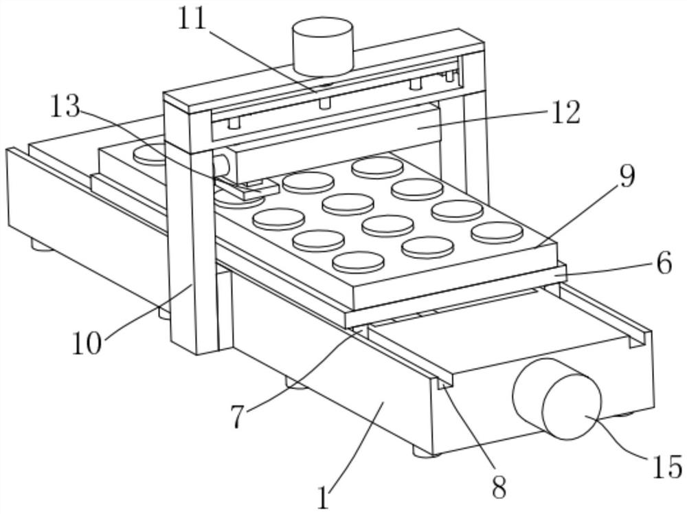
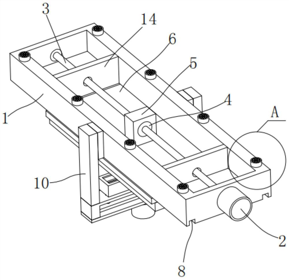
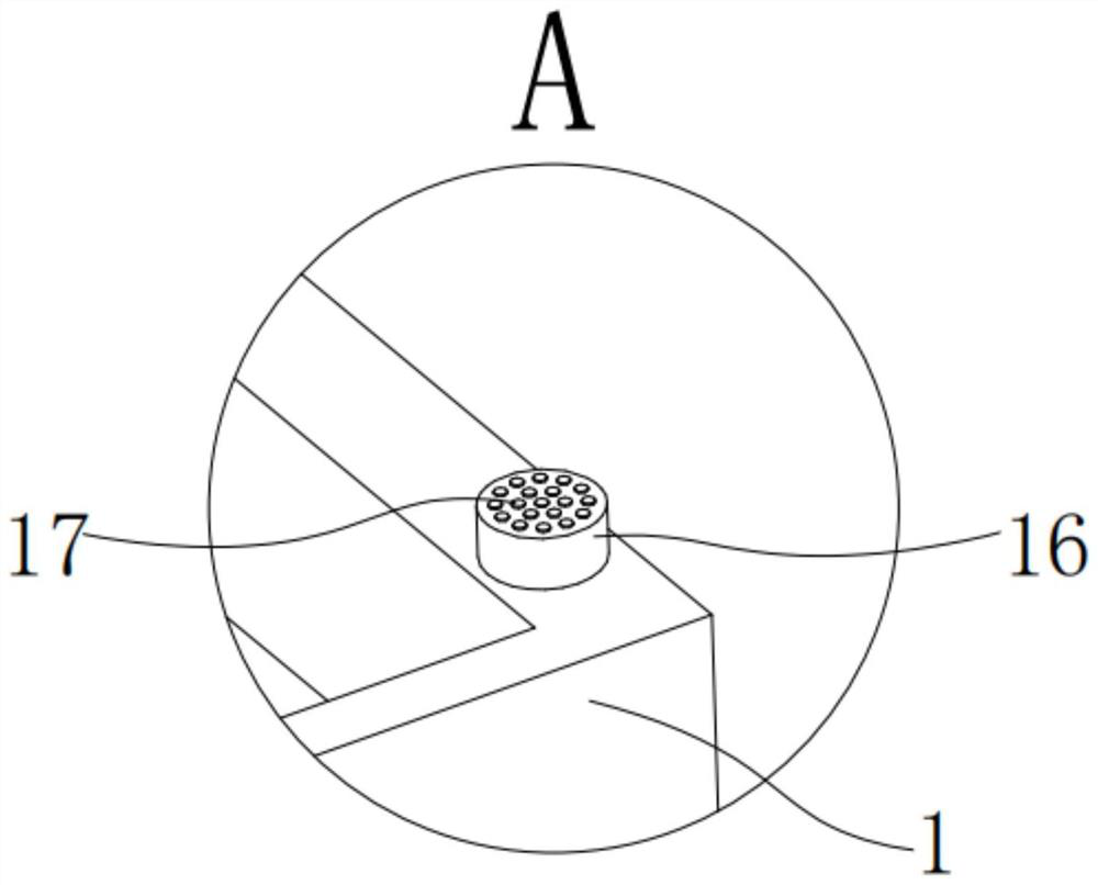
[0025] The present invention provides such Figure 1-5 The shown displacement adjustment device for grinding optical lenses includes a fuselage 1, a first servo motor 2 is fixed on one side of the fuselage 1 by bolts, and the end of the output shaft of the first servo motor 2 is fixed with a The first threaded mandrel 3, the end of the f...


PUM


Abstract

The invention discloses a displacement adjusting device for optical lens polishing. The displacement adjusting device comprises a machine body, wherein a first servo motor is fixed to one side of themachine body; a first lead screw is fixed to an output shaft of the first servo motor; the first lead screw is in threaded connection with a first transmission nut; the first transmission nut is embedded in a first mounting block; a workbench is fixed to the upper end of the first mounting block; first sliding blocks are arranged at two sides of the lower end of the workbench; each first sliding block slides in one first sliding groove; the first sliding grooves are formed in the upper end of the machine body; a lens placing jig is fixed to the workbench; support frames are fixed to two sidesof the machine body; a height adjusting mechanism is arranged at the upper ends of the support frames; a front-back adjusting mechanism is arranged on the height adjusting mechanism; and a grinding head body is arranged on the front-back adjusting mechanism. Through the structure, adjustment of an optical lens in the X, Y and Z directions in the polishing process is achieved, the structure is simple in structure, and operation is convenient.

Description

technical field [0001] The invention belongs to the technical field of lens grinding displacement adjustment devices, and in particular relates to a displacement adjustment device for optical lens grinding. Background technique [0002] Optical lenses are mixed with high-purity oxides of silicon, boron, sodium, potassium, zinc, lead, magnesium, calcium, barium, etc. according to a specific formula, melted in a platinum crucible at high temperature, stirred evenly with ultrasonic waves, and removed air bubbles, and then subjected to long-term Slowly cool down over time to avoid internal stress in the glass block. The cooled glass block has excellent properties such as transparency, uniformity, refractive index and dispersion rate, and has been widely used in the field of optical lens technology. In recent years, with the continuous development of science and technology, especially in the fields of biology, electronics, and chemical industry, higher requirements have been put ...

Claims


Application Information

Patent Timeline
Patent Type & Authority Applications(China)
IPC IPC(8): B24B13/00B24B13/005B24B47/20B24B47/22B24B47/04
CPCB24B13/0018B24B13/0031B24B13/005B24B47/04B24B47/20B24B47/22
Inventor 官晟文
Owner 上饶市晶鑫光学元件有限公司
Learn More